")
The two main types of motion in the context of mechanical engineering and motion control are rotary and linear. Although the enormous majority of prime movers, electric motors, internal combustion engines, and turbines, produce rotational motion, the physical world frequently needs straight line motion or linear movement. We have to move desks, gates, solar panels, and medical equipment.
This energy conversion device is a linear actuator.
This discussion will seek to give a critical analysis of the linear actuator. We are going to break down its basic design and working mechanics, compare the unique benefits of the electric systems to pneumatic linear actuators and hydraulic systems, and assess the most important specifications that should be met to select the system components correctly. In addition, we shall discuss the structural weaknesses that cause mechanical failure and lastly, how high precision engineering can solve these reliability issues.
The Basics: Definition and Core Function
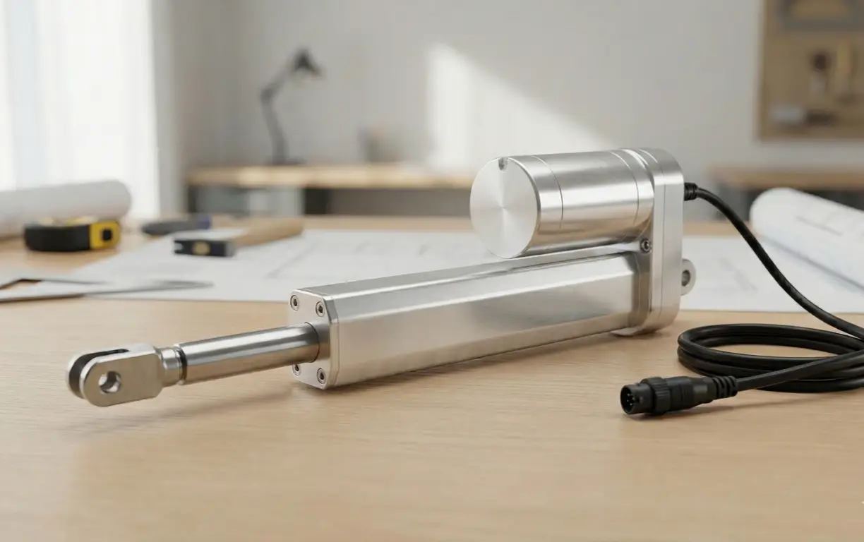
In its simplest form, a linear actuator is a mechanical tool that transforms energy from an external power source—whether electrical, hydraulic, or pneumatic—into linear movement. It produces a force or a pull or push on one axis.
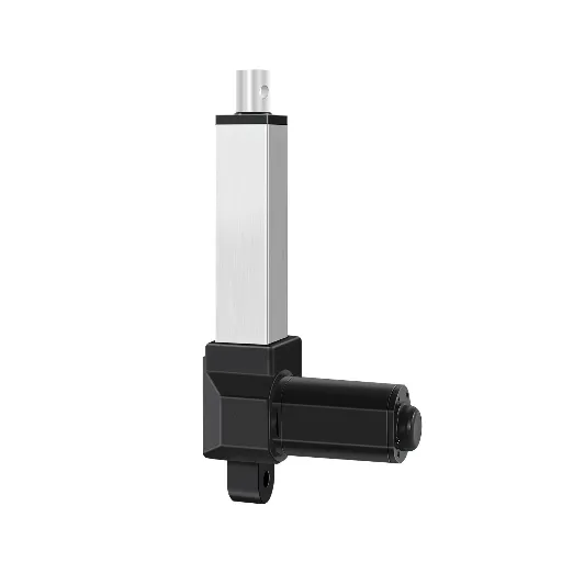
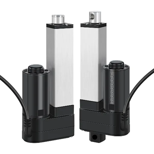
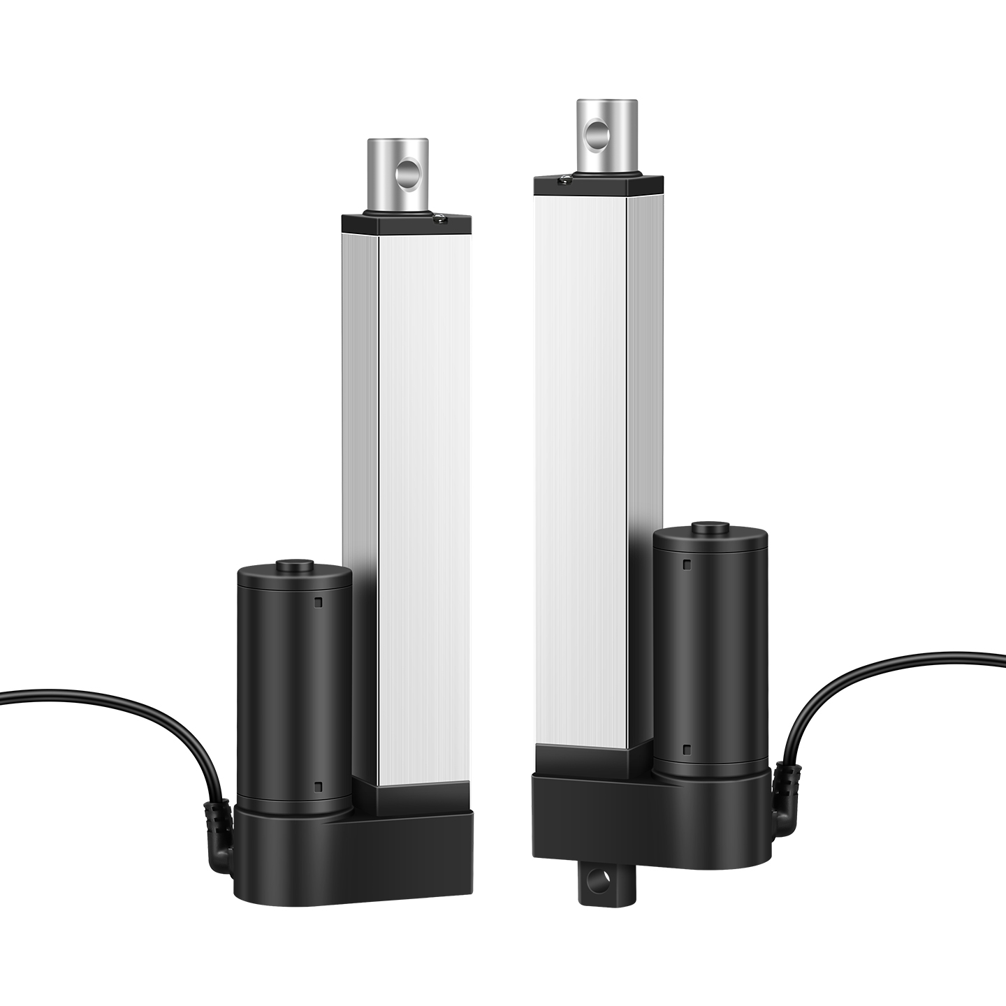
The most common use of the term in modern industrial and consumer applications is in reference to the electro mechanical linear actuators. It is a device that combines an electric motor, a gear reduction system, and a lead screw assembly to produce force. While mechanical actuators like rack and pinion systems exist, the electric variants are dominant.
Linear actuator utility is in the fact that it allows accurate control of position, speed, and force. A linear actuator can provide variable positioning anywhere in the stroke length, unlike a simple solenoid, which provides binary (on/off) positioning. This is needed in closed-loop control systems where feedback on the precise position of the load is needed.
Systems wise, the actuator serves as the connection between the control logic (software/electronics) and the physical environment (mechanics). It is through it that digital instructions are translated into physical motion, often working alongside rotary actuators in complex automation systems.
How Do Electric Linear Actuators Work? (The Mechanics)
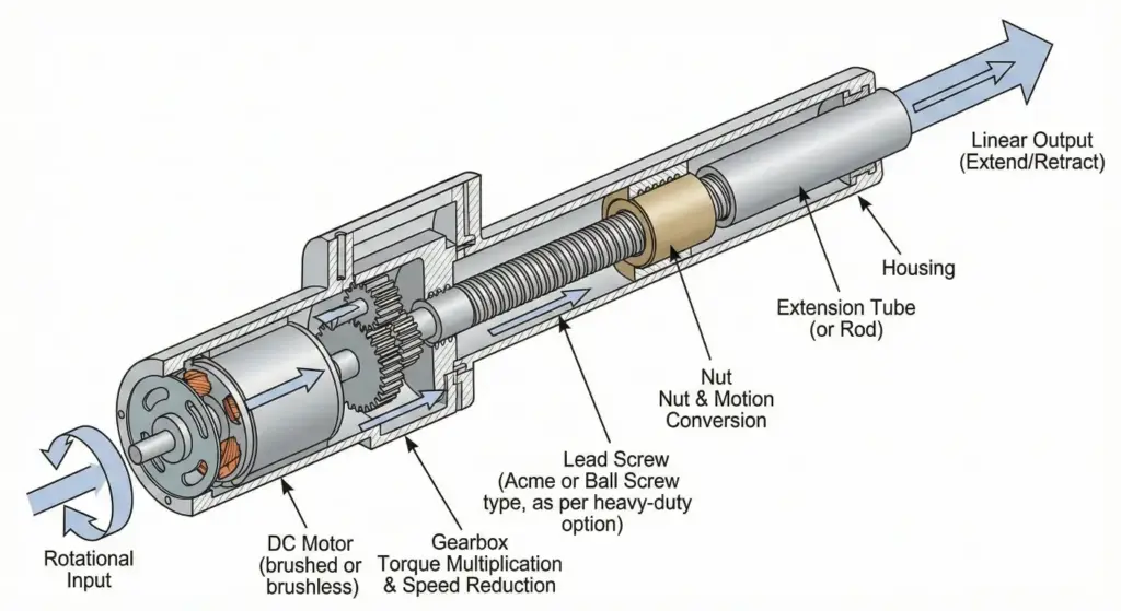
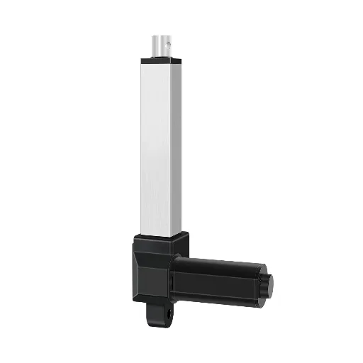
To understand the reliability and performance limits of an actuator, one must understand the internal transmission of force. An electric linear actuator, often designed as an electric cylinder or rod actuators, operates through a sequence of energy conversions:
- The DC Motor (Rotational Input): The process begins with a DC motor (brushed or brushless). When voltage is applied, the rotor spins at a high velocity—often several thousand revolutions per minute (RPM)—but with relatively low torque.
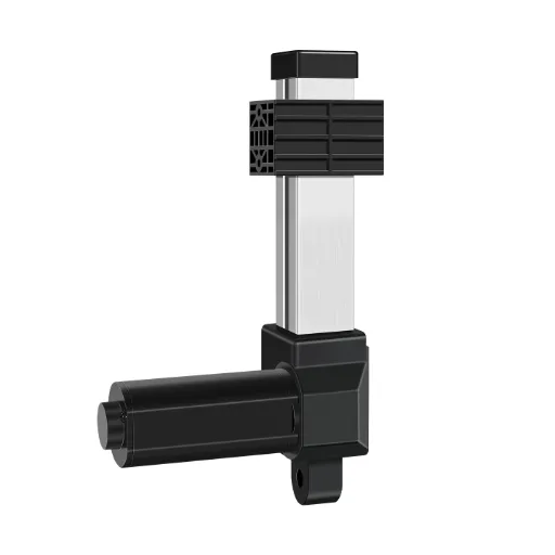
- The Gearbox (Torque Multiplication): This high-speed, low-torque rotation is fed into a gearbox. The gears serve two purposes: they reduce the rotational speed and, according to the principles of mechanical advantage, proportionally increase the torque. The material and precision of these gears are the primary determinants of the actuator’s acoustic signature (noise level).
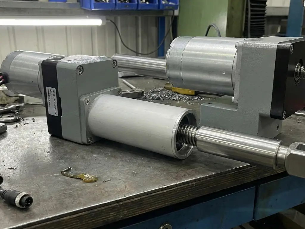
- The Lead Screw and Nut (Motion Conversion): The gearbox drives a lead screw. As the screw rotates, a nut is forced to move linearly along the threads. For high forceand heavy-duty industrial machinery, a roller screw may be used instead of a standard lead screw to handle higher stress.
- The Extension Tube: The nut is attached to an extension tube (or rod). As the nut travels up the screw, the rod extends from the housing; as it travels down, the rod retracts.
The Principle of Self-Locking
A critical mechanical feature of most screw-driven electric actuators is the static load capacity or self-locking ability. When power is cut to the motor, the actuator should ideally hold its position under load.
This is governed by the physics of the screw threads. If the lead angle of the screw is sufficiently low, the friction between the nut and the screw threads prevents the load from back-driving the system. This eliminates the need for external braking systems in many applications, simplifying the design and improving safety. However, not all actuators are self-locking; those with high-efficiency ball screws often require a separate brake mechanism to prevent back-driving.
Comparing the 3 Main Types: Electric vs. Hydraulic vs. Pneumatic
Although this analysis is about electric actuation, there is the need to put this in context of the larger discipline of motion control. The decision on the use of electric, hydraulic, and pneumatic systems depends on the force density, speed, and maintenance infrastructure needs.
The reason Electric Systems are replacing hydraulics
Over the past few decades, electromechanical actuation, commonly known as electrification, has changed dramatically. This tendency is predetermined by a number of systemic inefficiencies of fluid power:
1. Control and Precision: Electric actuators have a higher positional accuracy. An electric system can be brought to a halt a few millimeters short of a target position with the addition of Hall effect sensors or potentiometers. Hydraulic systems are more challenging to control with this type of precision without costly servo-hydraulics because of fluid dynamics and valve latency.
2. Maintenance and Cleanliness: Hydraulic systems are likely to leak. The liquids involved are frequently toxic or may pollute the product (a serious failure in food processing or in medical practice). Electric actuators have no fluids to leak and are sealed so that they are virtually maintenance-free throughout their period of operation.
3. Energy Efficiency: A hydraulic system will normally have a pump that is constantly on to sustain pressure, and it will use energy even when the actuator is not in motion. Electric actuator only consumes power when it is in motion. When it ceases, the self-locking mechanisms retain the load at zero energy consumption.
When to Persevere with Hydraulic Power
It would be a mistake to say that electric actuators are better in every measure. High power and extreme loads are still the domain of hydraulics.
Because of the incompressibility of hydraulic fluid, cylinders can produce enormous forces. When an application needs to lift 50 tons—common in rugged applications like earth-moving equipment—hydraulic actuation is the economic solution.
Pneumatic and Piezoelectric Niches
Pneumatic linear actuators use air pressure supplied by air compressors or an electric compressor. They are typically applied in high-speed, low-force cases like nail guns or simple assembly lines. However, air compressibility makes high precision difficult.
On the other end of the spectrum are piezoelectric actuators. Utilizing the piezoelectric effect, these devices expand materials when voltage is applied. They offer extremely fine positioning (down to the nanometer) for linear stages in optics, though they have very short travel ranges.
| Feature | Electric Actuator | Hydraulic System | Pneumatic System |
| Power Source | Electricity (DC/AC Motor) | Fluid (Oil Pump) | Compressed Air |
| Force Capacity | Low to High (Up to ~10 tons) | Extreme (Up to thousands of tons) | Low to Medium |
| Position Precision | Very High (Microns) | Low (unless expensive servo-hydraulics used) | Low (Hard to stop mid-stroke) |
| Speed | Moderate | Moderate | Very High |
| Maintenance | None (Sealed Unit) | High (Fluid leaks, filter changes) | Medium (Air leaks, condensation) |
| System Complexity | Simple (Plug & Play) | Complex (Pumps, hoses, valves) | Complex (Compressor, tubing) |
| Cost | Medium | High | Low (Component cost) / High (Energy cost) |
Key Specifications: How to Select the Right Actuator
Selecting the right linear actuator is a calculated process of matching mechanical specifications to environmental constraints.
Dynamic Load vs. Static Load Explained
One mistake that is often made during system design is the confusion of dynamic load and static load.
- Dynamic Load: This is the force that the actuator has to overcome in order to move the object. It takes into consideration the force of gravity, friction and any counteracting force in the extension or retraction process. The dynamic load is the major stressor of the internal components, namely, the motor windings and gear teeth.
- Static Load: This is the weight that the actuator is able to hold when it is not in motion and when it is not powered. The dynamic capacity is generally lower than the static load capacity as explained in the case of self-locking.
- The Hazard: When an actuator is chosen on the basis of the static capacity only in a dynamic application, it will burn out the motor immediately or break the gear. The engineers need to determine the maximum force needed during the movement phase and not only the holding phase.
Duty Cycle & IP Ratings (Waterproof Standards)
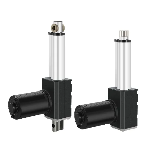
Duty Cycle is the ratio of on-time to off-time. Ignoring it leads to thermal failure. IP Ratings define resistance to solids and liquids. Compact linear actuators in clean rooms might need IP54, while outdoor industrial machinery requires IP65 or higher.
- Equation: Duty Cycle (%) = (Time On / (Time On + Time Off)) * 100.
Ignoring duty cycle leads to thermal expansion of internal components and degradation of the motor brushes, causing premature failure.
IP Ratings (Ingress Protection) define the enclosure’s ability to resist solids and liquids.
- IP20/IP42: Standard for indoor furniture (e.g., standing desks). Protection against dust and light drips.
- IP65/IP66: Required for industrial or outdoor use. These units are dust-tight and can withstand low-to-high pressure water jets.
- IP69K: The highest standard, required for equipment that undergoes high-pressure, high-temperature washdowns, such as in food processing or medical environments.
Common Failure Modes: Why Actuators Break?
It is also important to know why these devices fail as much as it is to know how they work. Field returns analysis normally indicates three main failure modes.
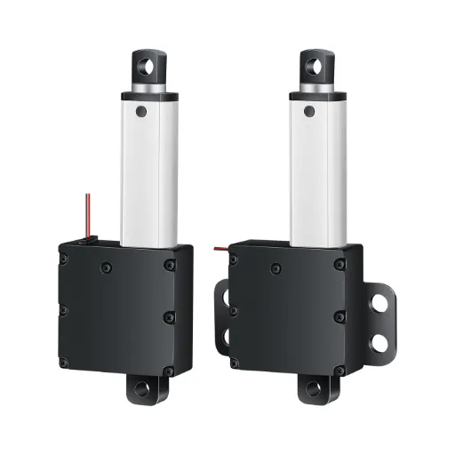
1. Side Loading (Radial Force): Linear actuators are developed to be able to push and pull in one direction. They are not made to resist side loads (shearing forces). When an application causes a radial force, such as when the mounting points are not aligned, the extension tube will become a lever arm. This curves the lead screw, raises friction and ultimately leads to the actuator binding or snapping.
2. Environmental Ingress: The common specification mistake is to use an IP42 actuator in an IP65 environment. When moisture gets into the housing, it emulsifies the grease on the lead screw and corrodes the internals of the motor. This causes more friction, more current flow and burnout of the motor.
3. Acoustic Degradation (Noise): Although not a disastrous mechanical failure, high noise levels are a functional failure in both medical and domestic settings. This is because of bad quality machining of gear or lack of lubrication. With the wear of gears, the mesh becomes loose, and the gears start vibrating and operating with high decibel levels.
Applications: Where are They Used?

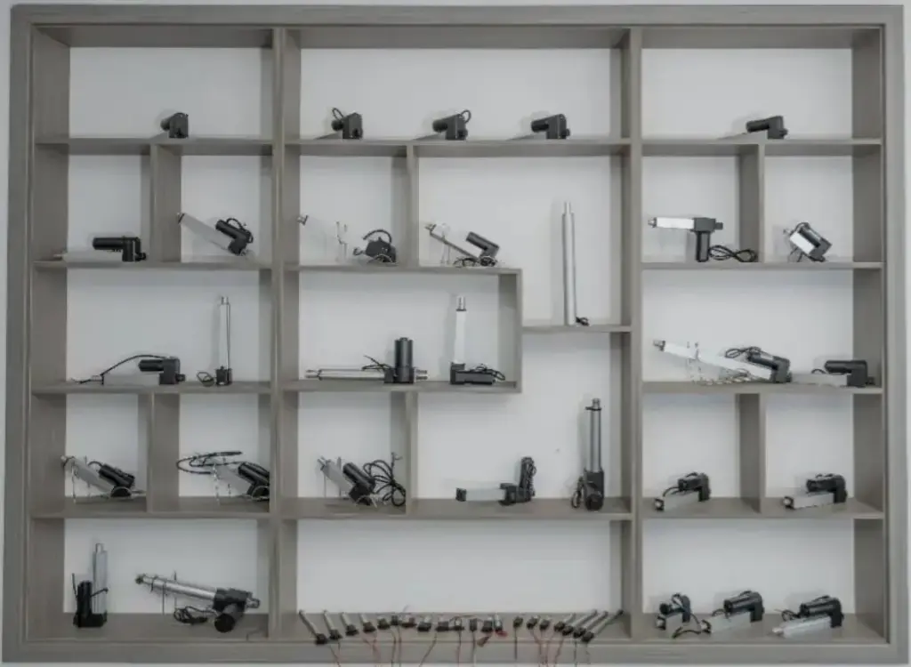
The linear actuator can be used in various industries with different operational needs because of its versatility.
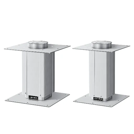
- Industrial Automation: In this case, durability and integration are considered. Actuators are used to control the operation of conveyor diverters, open heavy ventilation flaps in green houses and to control the movement of solar trackers.
- Medical and Healthcare: This industry requires high reliability and low noise. Actuators lift and lower hospital beds, patient lifts and MRI machines. The main consideration here is the safety and comfort of the patient.
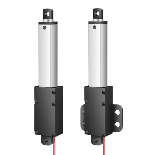
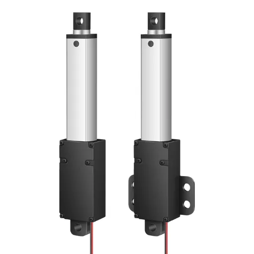
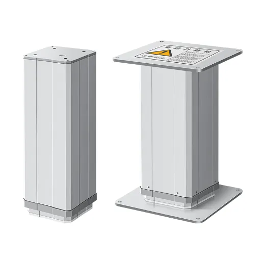
- Smart Home and Office: With the emergence of ergonomics, there has been a demand in electric sit-stand desks and adjustable beds. The shape (small size) and the visual incorporation are the most important in this industry.
- Automotive: Heavy-duty actuators are used to open tailgates, adjust seats, or deploy aerodynamic spoilers.
Why Hoodland? Engineering Precision & Custom Solutions
The above analysis points out an important fact a linear actuator can only be as reliable as its manufacturing tolerances and its applicability to the particular application. Off-the-shelf, standard components usually fail due to the inability to adjust to particular environmental stressors or installation limitations.
This is where Hoodland stands out.
Hoodland is not a producer of hydraulic or pneumatic systems; we are only a producer of electric linear actuators design and manufacture. Having a manufacturing history dating back to 1989 as a precision mold-making plant, Hoodland does not only treat electric actuation as an assembly problem, but as a precision engineering problem.
Whisper-Quiet Operation and 30,000+ Cycles
We have already noted acoustic degradation and premature burnout as the major failure modes. Hoodland deals with them at the root: the quality of components.
Hoodland has an outstanding precision in the manufacture of gear bits, which is made possible by extensive experience in the production of molds. This leads to Whisper-Quiet (<50dB) operation, a figure that competes with the sound level of a library. This renders the product line distinctively easy to fit in noise sensitive settings such as medical wards or luxury smart homes.
Moreover, reliability is not supposed, but it is proved. Each unit is subjected to a strict 2-hour Aging Test prior to shipment to avoid any defects of dead-on-arrival. Hoodland actuators have a design life of 30,000 cycles, and are designed to last longer than the equipment they drive.
True Customization: Beyond Standard Specs
A recurring issue for design engineers is the rigidity of standard catalog specifications. A project may require a specific stroke length, a non-standard speed, or a unique mounting orientation that generic products cannot accommodate.
Hoodland offers deep customization. Because the company owns its mold and processing workshops (covering 4,901 square meters), it can modify:
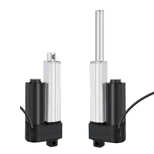
- Stroke and Speed: Tailoring the winding parameters and lead screw pitch to meet exact force/speed requirements.
- Installation Dimensions: Customizing the housing or mounting brackets to fit restricted spaces.
This flexibility is backed by a robust certification framework. Hoodland holds ISO9001 for quality management, alongside CE and RoHS compliance. Notably, specific models hold the Ex Certification (Explosion-proof), a rarity in the industry that validates the sealing and electrical safety of the units for use in hazardous environments involving volatile gases.
Conclusion & Next Steps
The linear actuator is the bridge between digital control and physical motion. Whether the application requires the massive force of a hydraulic replacement or the delicate, silent operation of a medical device, the physics of the selection process remain constant: match the load, duty cycle, and environmental protection to the hardware.
However, the difference between a functional system and an optimized system often lies in the customization and quality of the actuator.
If you are currently designing a motion system and require specific technical parameters that standard catalogs fail to provide, do not compromise your design.
Contact Hoodland today.
Our engineering team provides 1-to-1 selection advice to ensure your specifications—whether for “whisper-quiet” performance or hazardous environment protection—are met with precision. We pride ourselves on a “Fast, Not Rushed” response protocol, ensuring you receive the necessary CAD drawings and prototypes to keep your project on schedule.