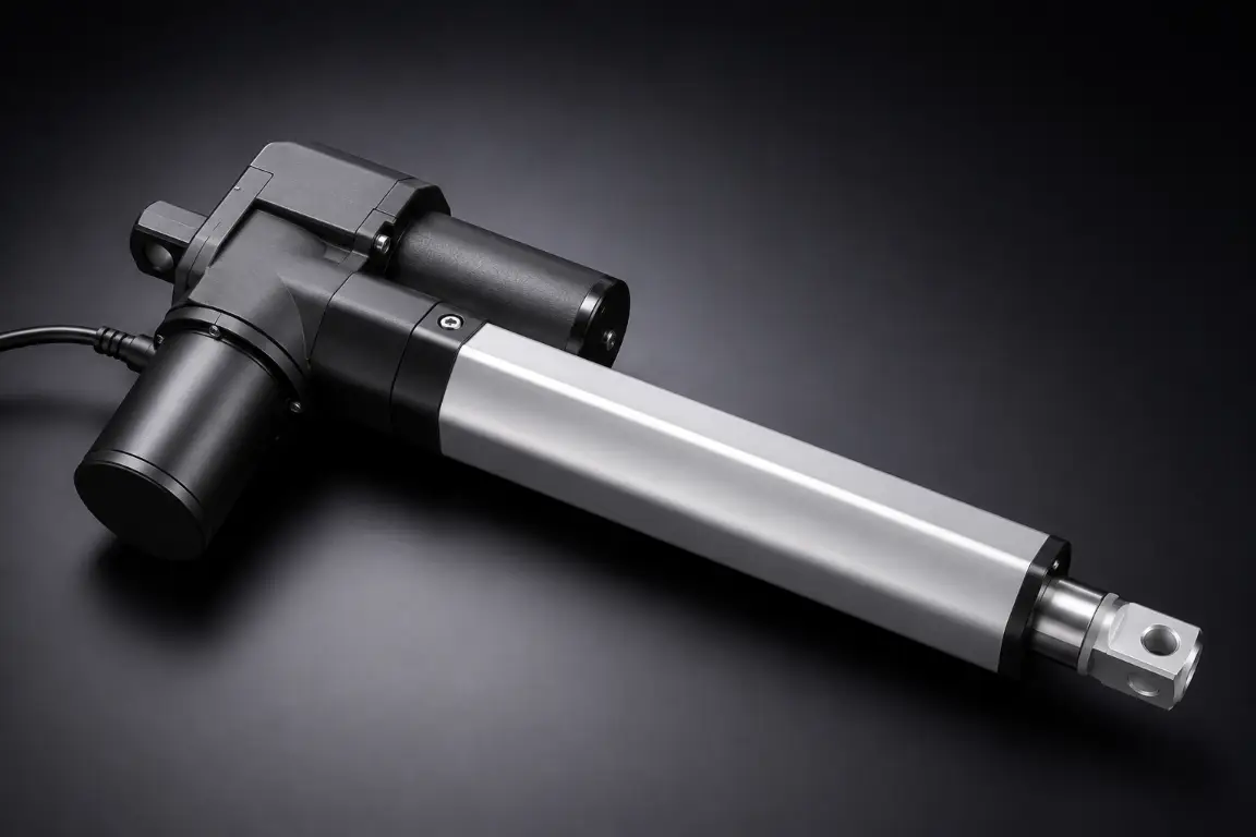
In the design of a mechanical system, the choice of the appropriate linear actuator is a very important choice that determines the reliability, safety, and durability of the whole machine. It does not matter whether you are developing solar tracking arrays, heavy-duty packaging equipment, or high-precision medical equipment, the forces that are going to act on your parts need to be carefully calculated. The load ratings are among the most important parameters that should be known.
When comparing dynamic load vs static load requirements, engineers and procurement managers often encounter two distinct specifications in manufacturer catalogs: Static Load Capacity and Dynamic Load Capacity. The inability to comprehend the significant disparities between static load vs dynamic load metrics is among the most common reasons of untimely equipment breakdown, disastrous structural destruction, and skyrocketing maintenance expenses.
This comprehensive guide will demystify the concepts of static and dynamic loads, explain the exact physical phenomena behind them, and provide actionable, step-by-step sizing strategies. By the end of this guide, you will understand exactly how these types of loads affect actuator performance, how to interpret manufacturer specifications accurately, and how to avoid the most common engineering pitfalls in linear motion control.
Core Definitions: Static vs. Dynamic Load Explained
In order to specify a linear actuator correctly, we need to first of all remove the marketing jargon and examine the basic physics of force application. The interaction between mass, gravity, acceleration, and time creates wildly different stresses on mechanical components. We classify these forces in structural design and mechanical engineering as mainly being either static or dynamic loads.
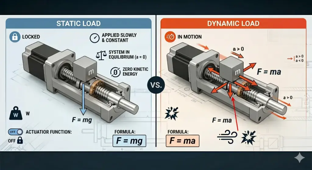
Static Load is a force that is applied slowly and remains a constant load in both magnitude, direction, and point of application over an extended period. In the context of physics, the system is in equilibrium; there is no acceleration (a = 0), and the kinetic energy of the load is zero. The most common example of a static load is the dead weight (or dead loads) of an object resting on a structure, governed simply by F = mg (where m is mass and g is the acceleration due to gravity). In the case of a linear actuator, this is the force that the unit must be able to sustain when fully stationary and off or mechanically locked.
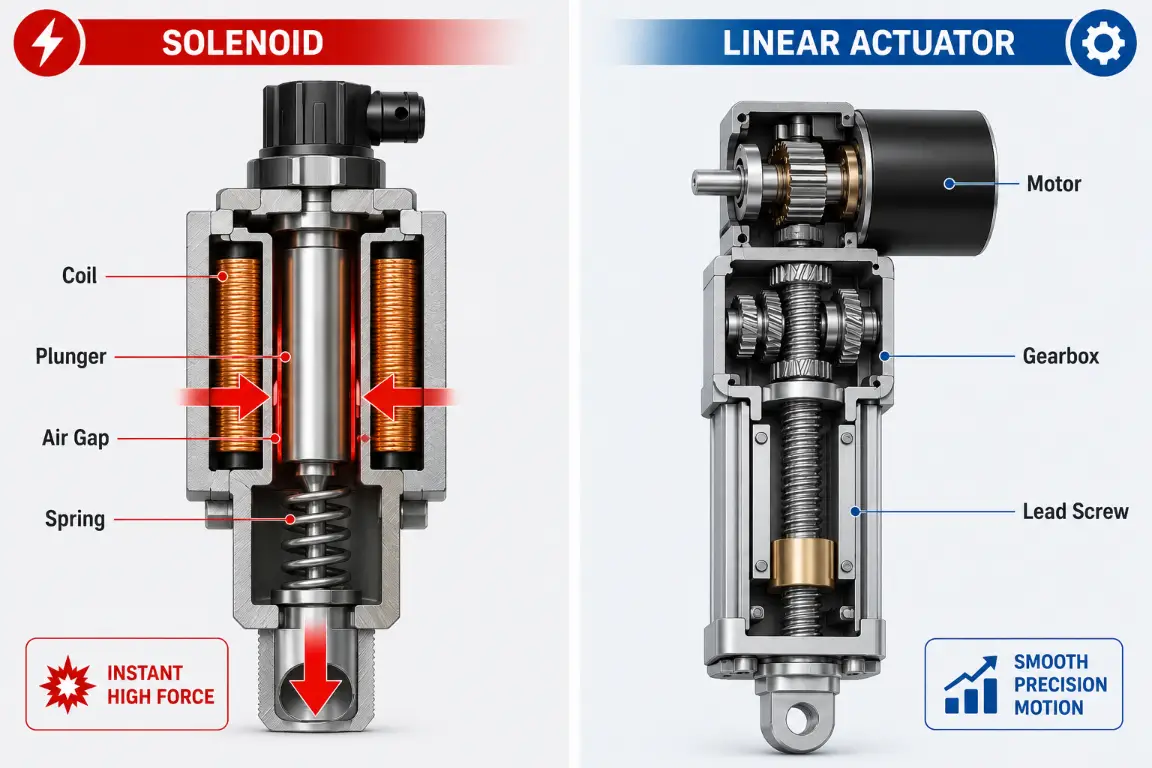
Dynamic Load on the other hand is a force which varies in magnitude, direction or position with time. This involves acceleration, deceleration, high frequency vibration (such as machinery vibrations) and abrupt impacts. Because the mass is in motion, Newton’s Second Law (F = ma) becomes the critical factor. The dynamic load is nearly always far more complicated and destructive than a static load of the same mass due to the inertia of the moving object, external dynamic factors such as friction, wind resistance, or mechanical shocks.
Common Misconceptions About Actuator Load Ratings
A widespread and threatening myth of mechanical design can be summed up as the “100kg holding vs pushing myth.” Most beginners designers think that when a linear actuator is rated to be able to support a 100kg weight, it can easily push or pull the same 100kg weight. This is a fatal engineering error.
The capability to support a mass in a static mode depends solely on the material strength and structural yield strength of the internal parts of the actuator, including the lead screw threads, the thrust bearings, and the outer housing. But when you start to push that 100kg mass, then you are not just dealing with gravity anymore. You are fighting inertia and friction.
The actuator has to overcome the friction of the stator (static friction) to move, and this is mathematically expressed as F_friction = μs * N, where mu s is the coefficient of statical friction and N is the normal force. Kinetic friction is always lower than the static one. Thus, when the actuator motor is switched on to move a 100kg block on a steel guide, it may take a similar dynamic force of 150kg to 200kg to overcome the stiction and get the mass moving to the desired speed. Moreover, when the load must be stopped in a short time, the deceleration produces a huge inertial spike. A 100kg mass that suddenly decelerates may produce a dynamic shock load that is exponentially greater than the weight of the object. The assumption of the equality of the static capacity with the dynamic one is bound to result in stalled motors, ripped gears, and bent internal shafts.
How Load Types Affect Linear Actuator Performance
The only way to master the art of linear motion design is to know how a linear actuator passes through various load conditions in a typical operating cycle. A linear actuator does not undergo a single mode of force, but it switches between a complicated profile of both static and dynamic stresses.
State 1: The Holding State (Static Dominance)
When the actuator is completely stopped and is holding a load in place, it is controlled by the static load capacity completely. As an example, when an actuator is employed to open and hold a heavy industrial skylight the weight of the glass and frame compresses the actuator shaft. The internal motor is usually switched off in this state. The load is held by the self-locking nature of the lead screw (acme thread) or an internal holding brake (common in ball screw designs). The performance metric here is purely structural: will the threads shear, or will the internal bearings deform under the constant pressure?
State 2: The Acceleration Phase (Dynamic Peak)
As soon as the motor is powered and starts to stretch or retract, the system switches violently between the static and dynamic. This is usually the most stressful part of a second in the lifecycle of the actuator. The motor must generate maximum torque to overcome the inertia of the resting mass, fight the high coefficient of static friction of the external guides, and accelerate the mass to the nominal travel speed. The current draw of the motor spikes, and the internal gearing experiences maximum shear stress.
State 3: Constant Velocity (Dynamic Steady-State)
Once the actuator reaches its target speed, acceleration drops to zero (a = 0). As long as the load is in motion, it is still a dynamic load, but the forces become stabilized. The actuator is currently struggling with kinetic friction (μk), which is less than static friction. But there are new dynamic variables: micro-vibrations of the motor, slight misalignment of the mounting brackets which lead to side-loading, and the rolling fatigue on the internal bearings.
State 4: Deceleration and Stopping (Dynamic Reversing)
At the end of the stroke of the actuator or when the actuator is ordered to cease, it is necessary to decelerate the moving mass. The kinetic energy of the load must be absorbed by the actuator’s drive train. If the stop is sudden (e.g., hitting a hard physical limit switch without a soft-stop control profile), the inertia of the load slams into the internal nut and bearings, creating a massive transient impact load. Once fully stopped, the system returns to State 1, resting under a static load.
Understanding Static Load Capacity (C0) in Actuators
When reviewing a linear actuator’s technical datasheet, the Static Load Capacity—often denoted as C0 in bearing and screw terminology—is a paramount specification. But what exactly does this number represent on a metallurgical level?
The maximum force that can be applied to the actuator (in the axial direction along the stroke) when at rest before the internal mechanical parts are permanently and irreversibly damaged is known as Static Load Capacity (C0). This is not the point where the actuator literally splits in half but it is the point of plastic deformation.
In linear actuators with ball screws or rolling-element thrust bearings, the international standard (including ISO 76) specifies the basic static load rating C0 as the load that causes permanent deformation of the rolling element and raceway at the most heavily loaded contact point which is 0.0001 times the diameter of the rolling element. Although 0.0001 is microscopic, such a deformation will entirely ruin the smooth functionality of the actuator. Once the actuator is then switched on, the ball bearings will roll across these tiny dents, resulting in intense vibration, appalling noise and catastrophic failure within a short time.
In actuators using trapezoidal or acme lead screws, exceeding the static load capacity usually manifests as the plastic yielding of the bronze or polymer nut threads. The threads will start stretching or shearing, and this will cause massive backlash (play) in the system, and ultimately, complete loss of load-holding capacity.
Safety requires the understanding of C0. When an actuator is fitted to a medical lifting bed, the capacity of the bed at rest will dictate whether the bed will safely support a bariatric patient when the power is switched off. It determines the integrity of the locked system. The engineers should make sure that the maximum weight, including the worst-case scenario of a person jumping on the bed or dropping a heavy tool on the machinery, should not surpass the C0 rating.
Evaluating Dynamic Load Capacity (C) for Movement
Whereas structural survival at rest is determined by the statical capacity, the lifeblood of the actuator in motion is Dynamic Load Capacity, which is denoted as C. It is the maximum load that the actuator can be sure to push, pull or control under load when it is in motion without experiencing premature fatigue failure.
Dynamic Load Capacity (C) is a complicated measurement since it is inherently related to time, distance, and the material properties governing material fatigue. In engineering terms, C is defined as the constant axial load under which a mechanical system (like a ball screw or bearing) can achieve a nominal life of one million revolutions (or a specified linear distance in kilometers) before the first signs of material fatigue appear.
In the case of dynamic loads, a number of important factors should be considered in precise engineering calculations:
- Duty Cycle (Operating Factor)
The duty cycle is very important in determining dynamic load ratings. Duty cycle is the proportion of operating time to resting time in a specified time. A linear actuator with a 2000N dynamic load at 10% duty cycle (e.g. 2 minutes of continuous running, 18 minutes of resting) cannot safely push the same 2000N when operated continuously at 100% duty cycle. The friction within it produces huge heat. Since dynamic movement generates constant friction, operating outside the recommended duty cycle will melt synthetic grease, swell internal metal parts leading to binding and ultimately burn out the DC or AC motor.
- The L10 Fatigue Life Calculation
In the case of precision actuators with ball screws, engineers employ the L10 life calculation formula to find out the exact lifetime of the actuator under a given dynamic load. The formula can be usually written as:
L10 = (C/P)^3 x 10^6 revolutions
Where:
- L10 = The basic rating life (where 90% of a sample population of the same bearings will still be in operation without fatigue).
- C = The basic dynamic load rating from the manufacturer’s datasheet.
- P = The equivalent dynamic load of your particular application.
This cubic relationship (C/P)^3 is brutal and unforgiving. It means that if you double the dynamic load applied to your actuator (P), the life expectancy (L10) does not just halve; it drops to one-eighth (1/2^3) of its original lifespan. It is this mathematical fact that makes the correct assessment of the dynamic load, as opposed to merely making a guess based on the static weight, the most important step in the design of linear motion.
- Impact and Acceleration Forces
In the assessment of C, the maximum forces during acceleration should be calculated. Assuming that an automated door is 50kg, the dynamic force needed to move it at 5mm/s is very minimal. However, to accelerate the same 50kg door to 500mm/s in 0.1 seconds, a huge dynamic force is needed to overcome inertia (F = ma). When this peak inertial force is greater than the dynamic rating C, micro-fractures will occur in the internal components with each start/stop cycle.
Common Actuator Failure Modes: Overloading and Fatigue
Physics comes into play when the careful calculations of both the static and dynamic loads are not taken into consideration and this leads to mechanical failure. The manner in which an actuator fails gives a clear forensic evidence of whether the actuator was overloaded in a static condition or fatigued in a dynamic condition. Knowledge of these failure modes enables engineers to troubleshoot the current issues and avoid them during the design.
Static Overload Failure: Brinelling and Yielding
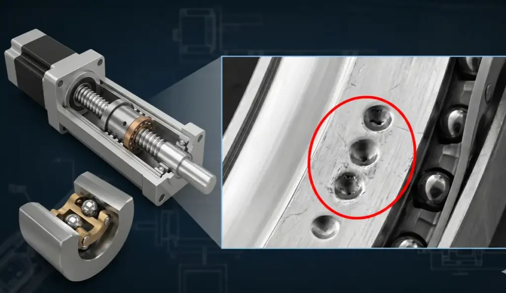
The failure is normally instant, noiseless and irreversible when the Static Load Capacity (C0) is surpassed. The most common manifestation in ball-screw actuators or thrust bearings is called Brinelling.
Brinelling is actually done by pressing the hard steel rolling elements into the soft steel raceways with a huge stationary shock (such as dropping a heavy die onto an idle stamping press) or a huge static force. This leaves distinct, permanent indentations (dents) at the exact spacing of the ball bearings. When brinelled, the actuator will produce a horrible grinding sound and shake violently when ordered to move.
In acme/trapezoidal lead screw actuators, static overload results in Thread Yielding or Stripping. The static force overcomes the shear strength of the nut material (often Delrin, bronze, or brass). The threads become deformed and lead to too much axial play and structural deflection. In extreme situations, the nut will strip away and the actuator rod will just fall back due to the load weight, which may cause disastrous accidents in lifting.
Dynamic Overload Failure: Flaking, Spalling, and Thermal Runaway
Failure is progressive and very destructive when an actuator is forced to operate a load greater than its Dynamic Load Capacity (C), or when it is operated at a duty cycle that is greater than its rated duty cycle.
Rolling Contact Fatigue (RCF) is the main mode of failure in dynamic overload and causes Flaking or Spalling. When the internal bearings and screws slide against each other with too much pressure, microscopic cracks start developing in the steel. Over millions of cycles, these cracks propagate to the surface. Small pieces of steel finally detach themselves either off the raceway or the ball bearings. This peeling substance pollutes the internal grease making it a very abrasive grinding paste, which quickly hastens the wear and tear of the whole drive train.
Another dynamic failure mode is Thermal Runaway. Pushing a dynamic load generates heat through friction. If the load is too high or the duty cycle too long, the heat cannot dissipate through the actuator housing fast enough. The inside temperatures are high and the lubricating grease is melting, the motor insulation is wearing out and finally the electrical windings short-circuit and burn out.
Industry Applications: Managing Loads in Real-World Scenarios
The theoretical distinction between the dynamic and the static loads is brought into sharp focus when it is applied to the strict industrial conditions. The engineering problems in different industries have their own engineering challenges where a single type of load is extremely dominant in the selection criteria. We will look at the way the real world determines the size of actuators.
- Solar Tracking Systems (High Static, Unpredictable Dynamic Impacts)
The speed of the solar panels is very low to follow the sun, which implies that the dynamic load of moving the panels is extremely low. But these systems are subjected to severe environmental conditions. Wind loading and sudden seismic activity are the major issues. A puff of wind on a huge system of solar panels is like a huge lever, and imposes a sudden, violent dynamic shock load on the actuator when it is at rest. In this case, engineers need to focus on a very high Static Load Capacity (C0) and make sure that the internal braking mechanism will be able to resist sudden impact forces without brinelling the internal parts.
- High-Speed Packaging Machinery (High Duty Cycle, Severe Dynamic Fatigue)
In automated packaging lines, actuators are used to push boxes, seal cartons, or divert products at lightning speeds. The static weight of a cardboard box is negligible. Nevertheless, the actuator may need to open and close twice per second, 24 hours a day. The continuous dynamic stress is formed by constant high acceleration and violent deceleration. In this case, the statical load rating does not matter much. The whole engineering emphasis should be on the maximum Dynamic Load Capacity (C) to achieve a high L10 fatigue life and a motor that can operate with a near 100% duty cycle without thermal breakdown.
- Sheet Metal Fabrication and Heavy Lifting (High Static, High Impact Dynamic)
The actuator is required to bear huge stationary loads of steel plates in such applications as hydraulic press brakes or heavy material handling platforms. Moreover, as the machine is running (e.g. a punch press hitting the metal), the shockwave is passed through the machine frame directly into the actuator shaft. This necessitates an actuator which is fundamentally constructed as a tank, with a huge C0 rating to carry the dead weight, and high dynamic strength to avoid internal shattering of the shockwaves.
Hoodland Solutions for Extreme Load Environments
In the severe industrial applications mentioned above, standard off-the-shelf actuators frequently succumb to premature fatigue, brinelling, or thermal failure. These complicated load issues demand the production of pedigree and deep customization. This is where Hoodland has the advantage as it has more than 30 years of experience in precision mold manufacturing to design industrial grade linear actuators that are specifically engineered to work in extreme load conditions.
In contrast to generic components, the actuator architecture of Hoodland is designed to support huge differences between the static and dynamic stresses. In heavy-duty lifting and industrial automation, the Hoodland IP6000 series provides an unbelievable thrust capacity of up to 6000N (around 600kg) with hardened steel internals and reinforced thrust bearings with an outstanding C and C0 rating. These units are strictly designed to eliminate the risk of thread yielding or ball-screw flaking under high-stress duty cycles.
Moreover, Hoodland deals with the crucial point of intersection of high load capacity and user experience. Hoodland applies its proprietary internal mold precision to perfect gear meshing in medical lifting beds or ergonomic smart desks, where the high static holding force and silent operation are the most important factors. This results in “whisper-quiet” operation at less than 50dB, effectively eliminating the harsh grinding noises typical of high-force actuators.
Reliability is not left to theoretical calculations. All Hoodland actuators have a long life of 30,000 cycles and are subjected to a 2-hour aging test and 100% quality test prior to leaving the 4,900-square-meter plant. Since standard parameters are seldom a perfect fit to complex engineering tasks, the in-house machining of Hoodland can be deeply customized, not only by changing the stroke lengths and speeds, but also by adding custom brackets and intelligent position feedback systems (Hall sensors/potentiometers) to ensure that the actuator is a perfect fit to your particular dynamic load profile.
Step-by-Step: Sizing Your Linear Actuator Correctly
Selecting the right linear actuator is not a guessing game; it is a methodical engineering process. In order to make sure that you do not undersize (and risk catastrophic failure) or oversize (waste budget and space) your actuator, this step-by-step sizing protocol will help you to properly assess the loads of your system.
Step 1: Determine the Pure Static Load (Dead Weight)
Calculate the absolute maximum weight the actuator will need to hold while fully stopped. Include the weight of the mechanism itself, the maximum payload, and any potential external weights (like ice buildup in outdoor applications). Make sure that this total weight is much less than the rated Static Load Capacity (C0) of the manufacturer.
Step 2: Map the Motion Profile to Calculate Inertial Forces
You have to decide how quickly the load should travel and more importantly how quickly it should accelerate to that speed. Use the formula a = Δv / Δt to find acceleration. Then, calculate the inertial force required to accelerate the mass using F_inertia = ma.
Step 3: Calculate Total Frictional Forces
Identify the friction in your guiding system. If your load is sliding on rails, multiply the normal force (weight) by the coefficient of sliding friction (μk). If the load is on wheels or linear profile rails, the friction will be much lower, but still present.
Step 4: Determine the Equivalent Dynamic Load (P)
Add your pure static weight (if lifting vertically), the inertial force required for acceleration, and the frictional forces fighting the movement.
P = F_gravity + F_inertia + F_friction.
This total sum is your Equivalent Dynamic Load. You must ensure that this number is well below the actuator’s rated Dynamic Load Capacity (C).
Step 5: Apply Engineering Safety Factors
Never design to the absolute limit of the catalog specifications. You must apply a safety factor (also known as a service factor) based on the operational environment. Multiply your calculated Equivalent Dynamic Load (P) by the appropriate safety factor from the table below to determine the final required dynamic rating.
| Application Environment | Shock / Vibration Level | Recommended Safety Factor | Example Scenario |
| Smooth, Indoor, Controlled | Very Low | 1.1 to 1.3 | Motorized standing desks, automated window openers. |
| Standard Industrial | Moderate | 1.4 to 1.7 | Conveyor belt diverters, standard packaging machinery. |
| Heavy Duty, High Cycle | High | 1.8 to 2.5 | Metal stamping feeders, continuous motion robotics. |
| Severe Shock / Outdoor | Extreme | 2.5 to 3.0+ | Solar trackers (wind load), agricultural machinery, heavy presses. |
Step 6: Verify the Duty Cycle and Speed Constraints
Lastly, examine the duty cycle graph of the manufacturer. Make sure that your necessary operating time is not too high to the thermal limits of the motor at your calculated dynamic load. If your application requires high speed and high load simultaneously, you may need to step up to a larger actuator frame size to dissipate the heat.
Need Custom Load Calculations? Ask Hoodland Experts
When it seems daunting to compute complex duty cycles, dynamic friction coefficients, or similar dynamic shock loads, then do not take a chance. The Hoodland engineering team offers free expert sizing calculations and complete system customization services. Hoodland will ensure that you have a linear motion solution that will work perfectly without over-engineering or sudden fatigue failure by examining your individual motion profile and load needs.
Engineering Best Practices for Load Management
Even the most robust linear actuator can be destroyed quickly if integrated poorly into the mechanical design. Managing loads is not just about picking a stronger actuator; it is about designing a smarter system. Implementing these engineering best practices will drastically extend the L10 fatigue life of your equipment.
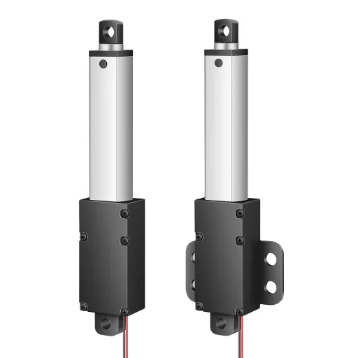
- Isolate the Actuator from Side Loads (Radial Loads)
Linear actuators are designed strictly to push and pull in a straight, axial line along their shaft. They are by no means intended to support side loads (radial forces). If a heavy load pushes sideways against the extended rod, it creates a massive bending moment. This destroys the internal seals, bends the lead screw, and results in serious uneven wear of the guide bushings.
Best Practice: External linear guides, profile rails or sliding tracks should always be used to support the physical weight of the moving carriage. Floating joints or spherical rod ends (clevis mounts) should be used to connect the actuator to the rails to ensure that it only provides pure axial thrust, with the external rails taking 100% of the side loads and rotational torque.

- Optimize the Motion Profile (S-Curve Acceleration)
The way you command the motor to move dictates the dynamic shock loads. A “trapezoidal” motion profile commands the motor to jump instantly to maximum acceleration, creating a violent jerk.
Best Practice: If using a smart controller, implement an “S-Curve” motion profile. This gradually ramps up the acceleration and smoothly ramps it down before stopping. Soft-starts and soft-stops remove dynamic impact loads that are transient, which greatly helps to prevent fatigue flaking of the internal ball bearings and maintain the C rating.
- Optimize Mounting Geometry
The mechanical leverage varies the force required with the angle of mounting an actuator significantly. When you are lifting a hinged trapdoor, having the actuator too near the hinge is like a short lever, and a huge dynamic force is needed to open the door.
Best Practice: Move the actuator mounting point as far away from the hinge or pivot point as the physical space allows. Maximizing the lever arm drastically reduces both the static holding requirement (C0) and the dynamic pushing requirement (C).
Frequently Asked Questions on Actuator Loads
To further explain the peculiarities of the linear motion design, the following are the responses to the most common questions posed by engineers and procurement teams concerning load ratings.
- Why is the Static Load rating (C0) almost always higher than the Dynamic Load rating (C)?
This comes down to the physics of material fatigue versus yield strength. A static load will only test the raw physical point where solid steel starts to bend or crush (plastic deformation). Steel in solid form is extremely strong in compressive stationary mode. Nevertheless, a dynamic load is a test that determines the capacity of the material to endure millions of rolling stress and friction cycles. Materials also fail (fatigue, micro-cracking and flaking) at significantly lower force levels than they do to direct, stationary crushing forces. Thus, the dynamic rating is never a larger, more liberal figure to guarantee a feasible lifespan.
- What is the difference between “Thrust” and “Load”?
While often used interchangeably in casual conversation, they are technically different in a physics context. “Load” is the external force being applied to the actuator by the environment (e.g., the 500N weight of a box pushing down). “Thrust” is the internal force generated by the actuator’s motor and screw mechanism to overcome that load. When sizing, your actuator’s rated thrust must be greater than the calculated equivalent dynamic load.
- Can I use the Static Load Capacity rating if my actuator moves extremely slowly?
No. This is a dangerous oversight. Even if an actuator is moving at 1 millimeter per second, it is still in motion. The internal forces are rolling, the grease is shearing and kinetic friction is at work. Rolling contact fatigue is brought about by any movement, however slow. Thus, you need to test the system with the Dynamic Load Capacity (C), but you will probably have a longer L10 life as the heat generation is lower at slow speeds.
- Does a higher Duty Cycle lower my Dynamic Load Capacity?
Yes, inversely. Manufacturers typically rate the dynamic load capacity at a specific duty cycle (e.g., 10% or 20%). By forcing the actuator to operate at a 50% duty cycle, the heat produced by the constant friction will reduce the effective viscosity of the lubricants and increase the size of the metal parts. To endure a larger duty cycle, you need to greatly derate the dynamic load capacity, and in many cases, you can only operate the actuator at 30% to 50% of its rated dynamic load to avoid thermal breakdown.