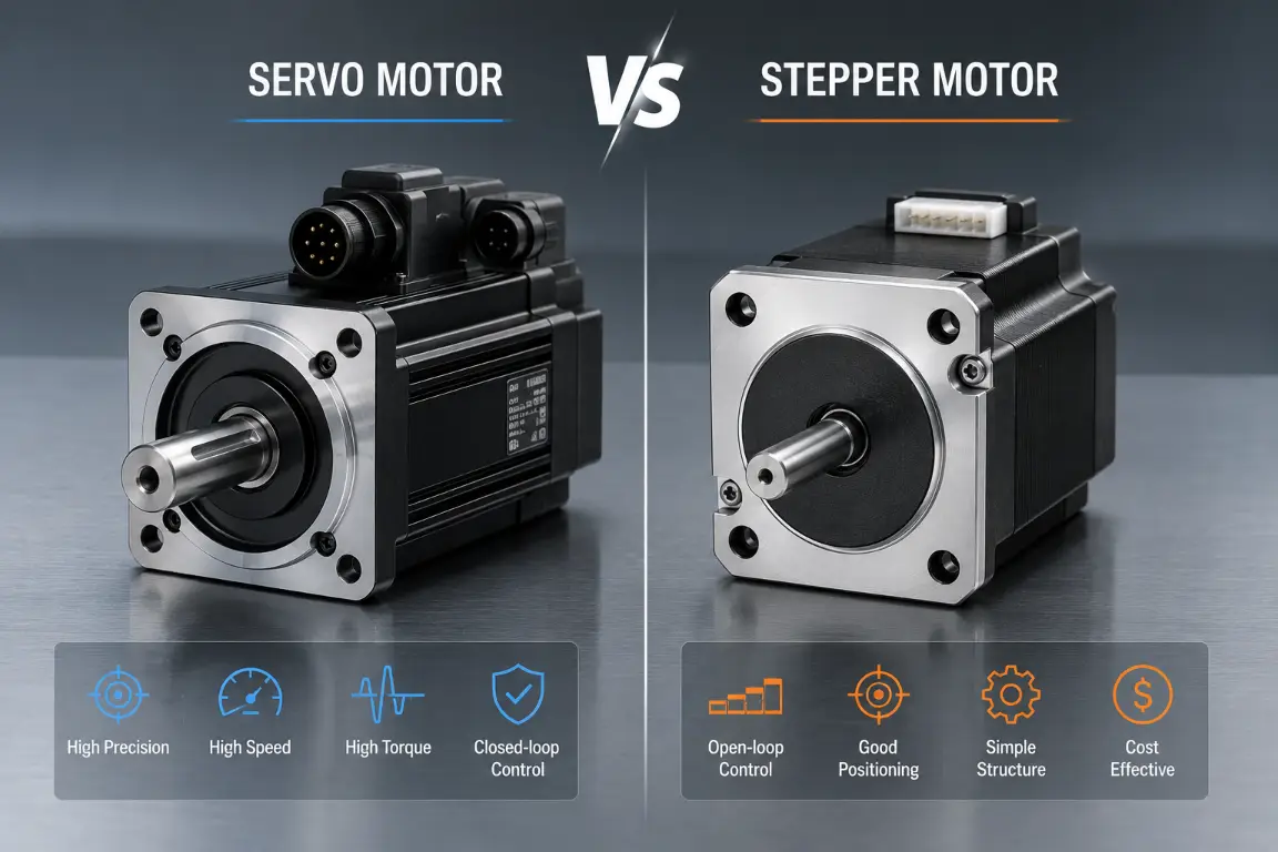
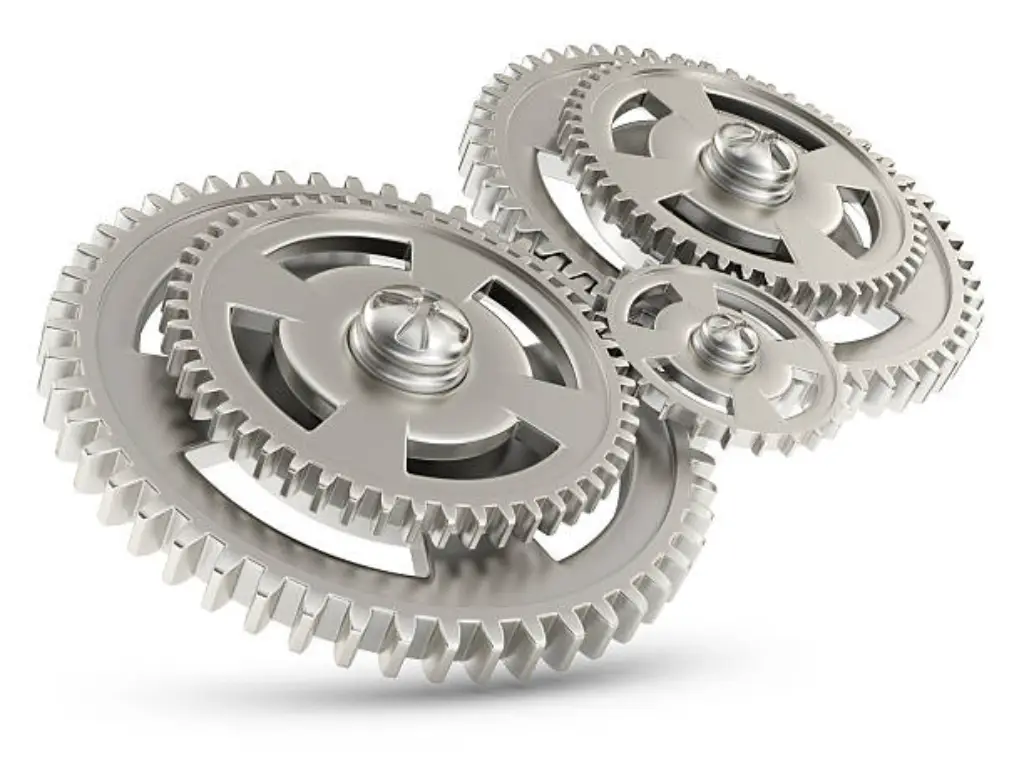
In the modern industrial automation world, a motor forms the basic backbone of virtually all machines. It does not matter whether you are working with a standard AC induction motor, a very fine stepper motor or a high-performance servo drive, the mechanical output is always the same: rotary motion. The real physical work on a factory floor, pushing, pulling, lifting, pressing, cutting and positioning payloads, however, overwhelmingly requires controllable linear motion.
It takes deep engineering ingenuity to fill this gap of criticality. It is not just a simple physics problem to convert rotary to linear motion, but rather a high stakes decision making process that determines the ultimate precision of a machine, its maximum speed, load capacity and its overall life cycle. Making the wrong mechanical transmission system choice may cause disastrous mechanical failures, intolerable manufacturing tolerances, or undue maintenance downtimes that bring production lines to their knees.
This comprehensive guide explores the core mechanics of the entire conversion mechanism, evaluates the most dominant transmission systems used in heavy-duty applications, and provides a definitive framework for selecting the right motion components for your next automation project.
Core Mechanics of Rotational to Linear Motion Conversion
In its simplest form, rotational to linear motion conversion requires the conversion of angular velocity and torque to linear velocity and linear force (thrust). The rotating shaft produces the input and the output is provided on a single, straight line constrained axis.
To see this conversion, it is necessary to consider the simplest physical relations and implementation details. For a simple rotary-to-linear system, the theoretical linear velocity (v) is directly related to the angular velocity (ω) and the effective radius (r) of the driving component, expressed by the formula:
v = ω * r
Similarly, the linear force (F) generated is a function of the input torque (τ) and the mechanical advantage of the system. For systems like lead screws, the force transmission factors in the pitch (p) and the efficiency (η) of the system:
F = (2 π τ * η) / p
In real-world engineering, this conversion is never perfectly efficient. Friction, inertia, material elasticity, and mechanical clearances (often referred to as backlash) all absorb energy, generate excess heat, and introduce positional inaccuracies. The ultimate goal of mechanical design is to select a conversion mechanism that minimizes these inherent losses while maximizing the specific trait needed for the application—be it the heavy lifting capability of a hydraulic-like system, the lightning-fast speed of a synchronous belt drive, or the microscopic, sub-millimeter precision of a high-end ball screw.
Crank, Slider, and Scotch Yoke Mechanisms Explained
Prior to the introduction of the complex computer numerical control (CNC) systems and sophisticated servo tracking, engineers used simple and purely mechanical linkages and follower mechanisms to provide linear movement. The crank-slider, crank-rocker and Scotch Yoke mechanisms are still among the most proven ways and most popular options of converting continuous rotation into reciprocating motion (a repetitive back-and-forth linear motion).
A Slider-Crank mechanism is made up of a crank (a rotating arm) mounted on a connecting rod, which is mounted in turn on a slider limited to a linear path. As the crank turns a full 360 degrees, the slider moves back and forth along its track. A similar effect is obtained by the Scotch Yoke mechanism, which substitutes the connecting rod with a sliding yoke with a perpendicular slot.
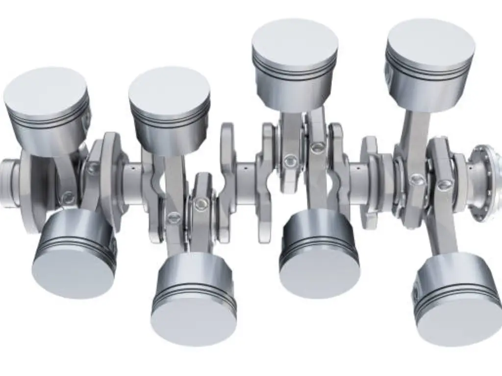
This particular design generates actual simple harmonic motion, which results in a highly smooth motion profile that minimizes mechanical shock at the ends of the stroke. A classic example can be found in a traditional internal combustion engine, where the linear piston motion within the engine block rotates the crankshaft, or conversely in a mechanical water pump.
These are legendary mechanisms in terms of their longevity and they are extensively used in applications where repetitive, continuous and reliable strokes of reciprocation are needed. A classic example can be found in advanced industrial packaging equipment, specifically in high-speed nitrogen flushing and sealing machines. In such complicated systems, the constant movement of the main drive motor has to be converted into the accurate, rhythmic up and down pressing motion of the heated sealing molds. The slider-crank mechanism ensures that the sealing die hits the exact same vertical dead center on every single cycle, applying uniform, calculated pressure to deliver consistent results and create an airtight seal without requiring complex electronic synchronization for the stroke itself.
Belt, Chain, and Pulley Systems for Long-Distance Travel
Traditional metal linkages and heavy steel screws are very impractical when an application needs to transfer a payload over a long travel distance at high speed, as they are very heavy, expensive to manufacture, and have very high limits to vibration (commonly referred to as “critical speed whip”). Belt and chain drive systems are really good here, especially when you need to achieve higher speeds with relatively moderate loads.
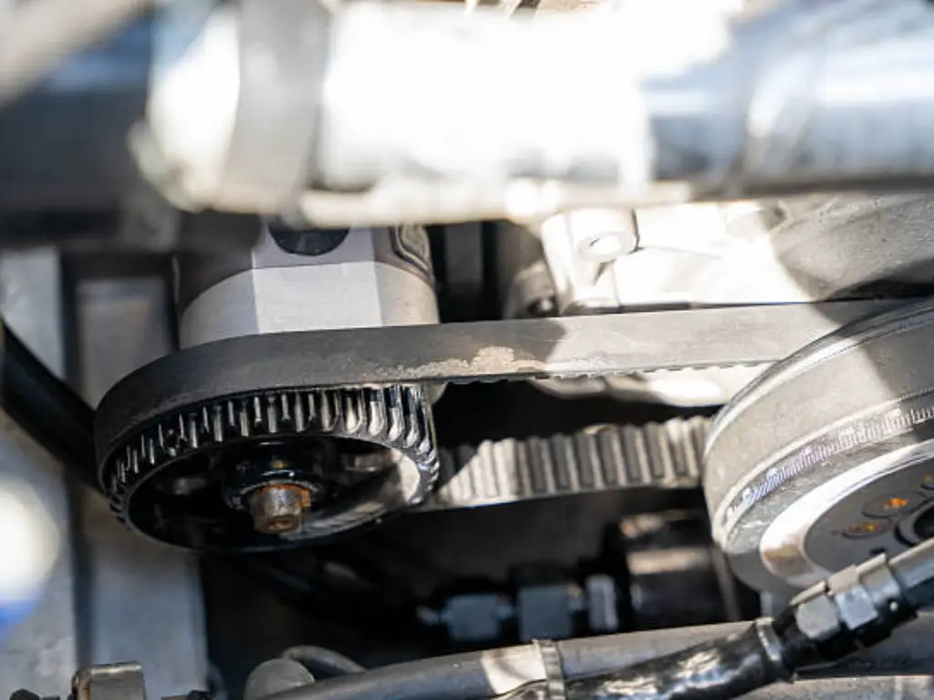
A synchronous timing belt, which is usually reinforced with internal steel or Kevlar tension cords to avoid stretching, is then stretched between a motorized drive pulley and an idle tensioning pulley in a belt-driven linear system. A carriage is attached to this belt, sliding smoothly along a linear profile rail. The belt pulls the carriage in a linear manner as the motor turns the drive pulley.
Advantages in Automation:
- Exceptional Speed and Length: Belt drives can easily achieve linear speeds exceeding 5 meters per second and can span continuous lengths of 10 meters or more without suffering from the sagging and whipping effects that plague long metal screws.
- Cost-Effective Scalability: For long-stroke material handling applications, extruded aluminum profiles and polyurethane belts are significantly more economical than machining massive, high-precision metal components.
- Low Maintenance Operations: Modern timing belts require absolutely no lubrication, resist chemical washdowns, and generate minimal wear debris, making them ideal for cleanroom or food-grade environments.
Inherent Limitations: Although they have absolute control in the material handling, the gantry robots, and the large conveyor lines in packaging, the belt and chain systems have inherent limitations in terms of extreme precision. Belts are subject to micro-elastic stretching under heavy acceleration or rapidly varying payloads. Chains suffer from chordal action (a slight, rhythmic pulsing movement as rigid chain links engage the circular sprocket) and wear-induced elongation over time. Thus, they are not as good in micro-machining or ultra-precise positioning, but are not replaceable in long-distance transport.
Lead Screws vs. Ball Screws: High-Precision Linear Motion
In situations where automation of industry requires high precision, extreme structural stiffness, and complete repeatability, screw-driven mechanisms are instantly considered by engineers to drive any specific mechanical device. These systems use a threaded metal shaft that is rotated by a motor, and this rotates a mating nut that moves in a linear manner along the length of the shaft. Nevertheless, two completely different levels of performance and cost are determined by the internal mechanical interactions of the nut, along with proper material selection.
Lead screw motion is completely dependent on sliding friction. The inside threads of the nut (usually made of bearing-grade bronze or special self-lubricating polymers such as Delrin) slide directly on the polished threads of the stainless steel screw. Although lead screws are much more cost-effective and can self-lock (which is an important safety feature to prevent the lead screw mechanism back-driving in case of a sudden loss of power), they have a greater friction. This produces a lot of heat at high speeds, needs greater torque of the motor and causes physical wear with time. Such wear is bound to cause mechanical backlash, the lost motion or physical play as the motor switches direction.
To properly specify these components, engineers must differentiate between Lead (the linear distance traveled in one full 360-degree rotation of the shaft) and Pitch (the linear distance between adjacent threads). In single-start screws, lead and pitch are identical. However, in multi-start screws, a larger lead can be achieved for faster linear travel without weakening the structural integrity of the thread profile.
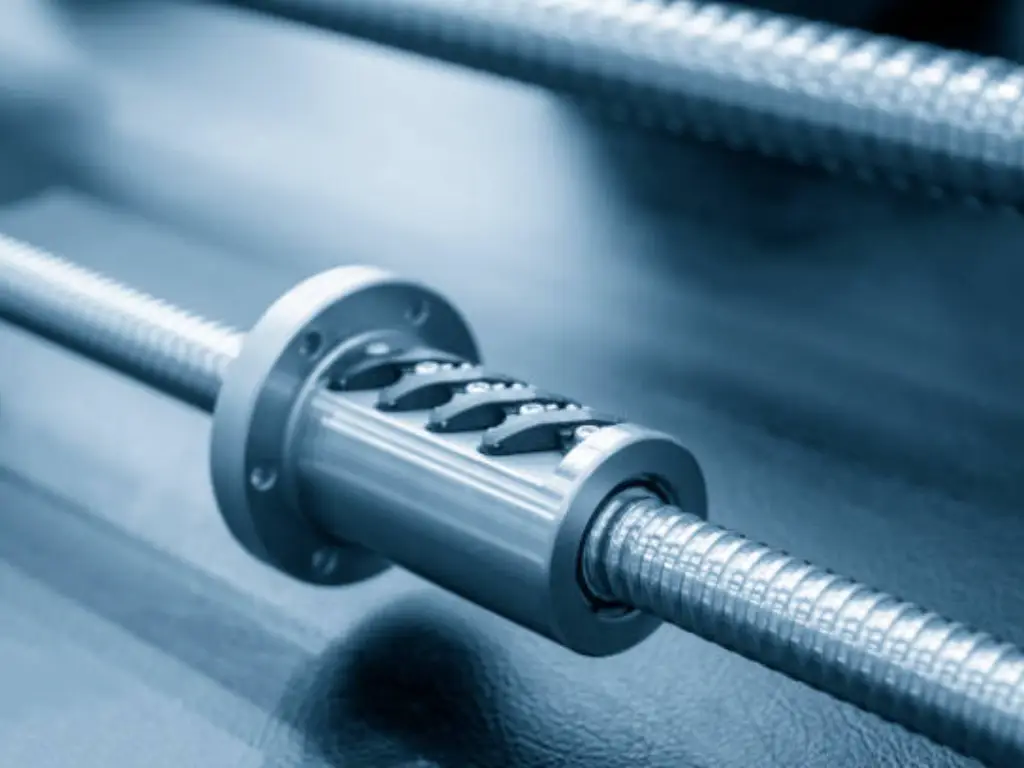
Ball Screws, on the other hand, represent the gold standard for high-precision motion control. Instead of sliding friction, ball screws utilize rolling friction. The specialized nut is filled with steel ball bearings which are machined to a high level of precision and which circulate in the hardened thread grooves between the screw shaft and the nut.
This rolling motion practically removes friction, and mechanical efficiencies of up to 90% are attained. Moreover, it enables manufacturers to physically “preload” the nut with oversized ball bearings, which completely removes mechanical backlash. Such high accuracy and very smoothness are essential when dealing with delicate, high-value cargo in highly demanding precision applications.
Take an example of an automated cosmetic or beverage assembly line that is required to handle special glass perfume, liquor, and skincare bottles. Exact positioning is not a luxury; it is a strict requirement. The zero-backlash, extremely smooth travel of a high-end ball screw is what makes the automated robotic grippers and high-speed filling nozzles fit perfectly into the narrow, delicate necks of these special glass containers. It guarantees precision without the sudden jerks or micro-vibrations that would easily crush or misalign fragile glass during high-volume capping and filling operations.
Rack and Pinion Systems for Heavy-Duty Applications
In engineering uses where the long-range travel of a belt drive is required, as well as the high-thrust, push/pull nature of a screw drive, the rack and pinion system is the final, no-compromise solution. This is a robust mechanism that is composed of a rotating gear (the pinion) that is in perfect contact with a linear, flat gear, the gear rack. The precise meshing of the gear teeth ensures robust power transfer. The high-torque motor is self-driven (or the heavy carriage attached to it) as it rotates the pinion, moving along the entire length of the rack.
Rack and pinion systems are associated with high-impact, heavy-duty machinery. Since the steel rack is firmly attached to the huge machine frame, it is not subject to the tension stretching of belts, and it is not subject to the severe speed whipping constraints of long ball screws.
They are also extensively used in large-scale CNC plasma cutters, huge robotic seventh-axis transfer tracks, and extremely demanding outdoor applications. One of the best examples of their ruggedness is in automated outdoor marine infrastructure, namely in automated extension structures on modular floating dock cubes. Engineers have to deal with the most extreme environmental and physical conditions when designing automated ramp retraction systems or mechanical deployment arms to drive-on PWC (Personal Watercraft) docking platforms.
The mechanism has to provide huge linear force to propel heavy, water-logged vessels up a gradient and at the same time withstand highly corrosive saltwater spray, huge wind forces and constant structural distortion due to the wave action. A massive, highly lubricated rack and pinion system offers the brute force and environmental durability of sheer mechanical power needed in situations where sensitive ball screws would soon seize or break.
NEMA and IP Rating Standards for Motion Components
It is half the engineering battle to convert rotational to linear motion, the other half being to make the mechanical assembly endure the harsh unforgiving realities of any heavy-duty manufacturing process on an industrial factory floor. When specifying motors, gearboxes, and linear motion components, understanding and applying industrial protection standards is non-negotiable for extending the service life of the equipment.
IP (Ingress Protection) Ratings internationally define exactly how well a mechanical housing protects its internal electrical components and lubricated moving parts from solid ingress (dust/debris) and liquid ingress (water/coolants).
- An IP54 rating offers basic protection against standard dust and splashing water, suitable for clean, indoor, climate-controlled assembly lines.
- An IP60 rating provides total, vacuum-tight protection against fine dust ingress but no protection against water. This is often utilized in dry, heavily particulate-laden environments like woodworking or textile manufacturing.
- For aggressive washdown environments (like strict food processing facilities) or severe outdoor marine applications, ratings of IP65 (low-pressure water jets) or IP66 (powerful, high-pressure water jets) are mandatory to prevent motor coils from shorting out and precision gears from rusting.
Furthermore, standardization of the motor interface is crucial for maintenance and sourcing. NEMA (National Electrical Manufacturers Association) standards dictate the exact physical frame sizes, shaft diameters, and mounting hole patterns of motors (e.g., NEMA 17, NEMA 23, NEMA 34). By making sure that your linear actuator, gearbox and rotational motor are all designed to NEMA standards, you can be sure that you can find replacement parts everywhere and that a failure by one proprietary motor manufacturer will not bring down an entire production machine that you have built to order.
Electric Linear Actuators: The Ultimate Integrated Solution
It is important to note that before delving into the final solution, it is important to consider the nightmares that equipment manufacturers go through when they want to construct their own linear motion systems. To obtain a motor, a ball screw, a gearbox, and a controller individually is likely to cause the multiplication of engineering headaches, increasing your overall integration effort and development time:
- The Alignment Nightmare: To mount a high-speed rotary motor to a fine linear screw, it is necessary to be microscopically accurate. Even a fraction of a millimeter of careful alignment error introduces severe side-load stress, leading to premature bearing wear, excessive heat generation, and sudden, catastrophic mechanical binding.
- The Hidden Costs of IP Protection: A raw, exposed ball screw or a standard rack and pinion cannot survive in a dusty industrial shop or a sterile washdown medical environment. Designing, fabricating, testing, and verifying custom protective bellows and sealed motor enclosures to achieve strict IP65 or IP66 ratings drains massive amounts of engineering hours and project budget.
- The “Tractor” Noise Factor: Conventional industrial motion systems are concerned only with raw thrust, and in many cases do not even consider acoustics. The loud whining of bare gears and the whine of the motor are totally unacceptable in modern medical beds, ergonomic dental chairs, or the expensive smart home furniture.
- Synchronization Headaches: Trying to make two separate DIY screw systems lift a heavy, asymmetrical platform perfectly in sync without twisting the structural frame usually requires complex, expensive external PLC programming and delicate external encoders.
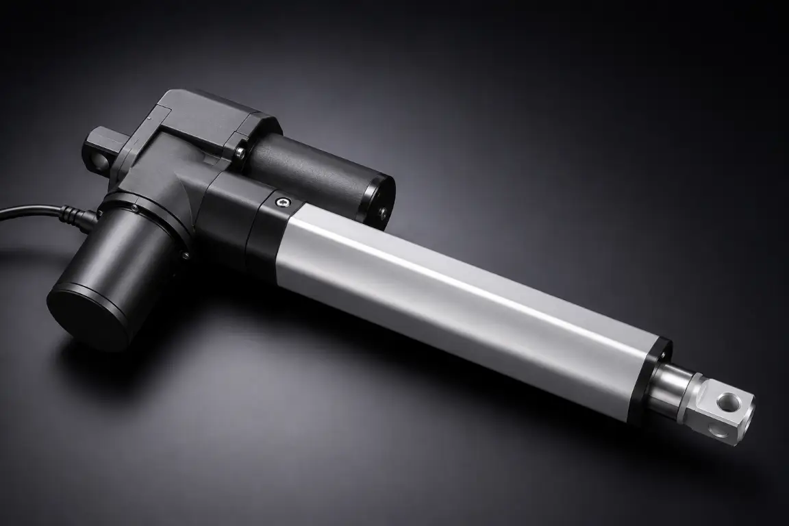
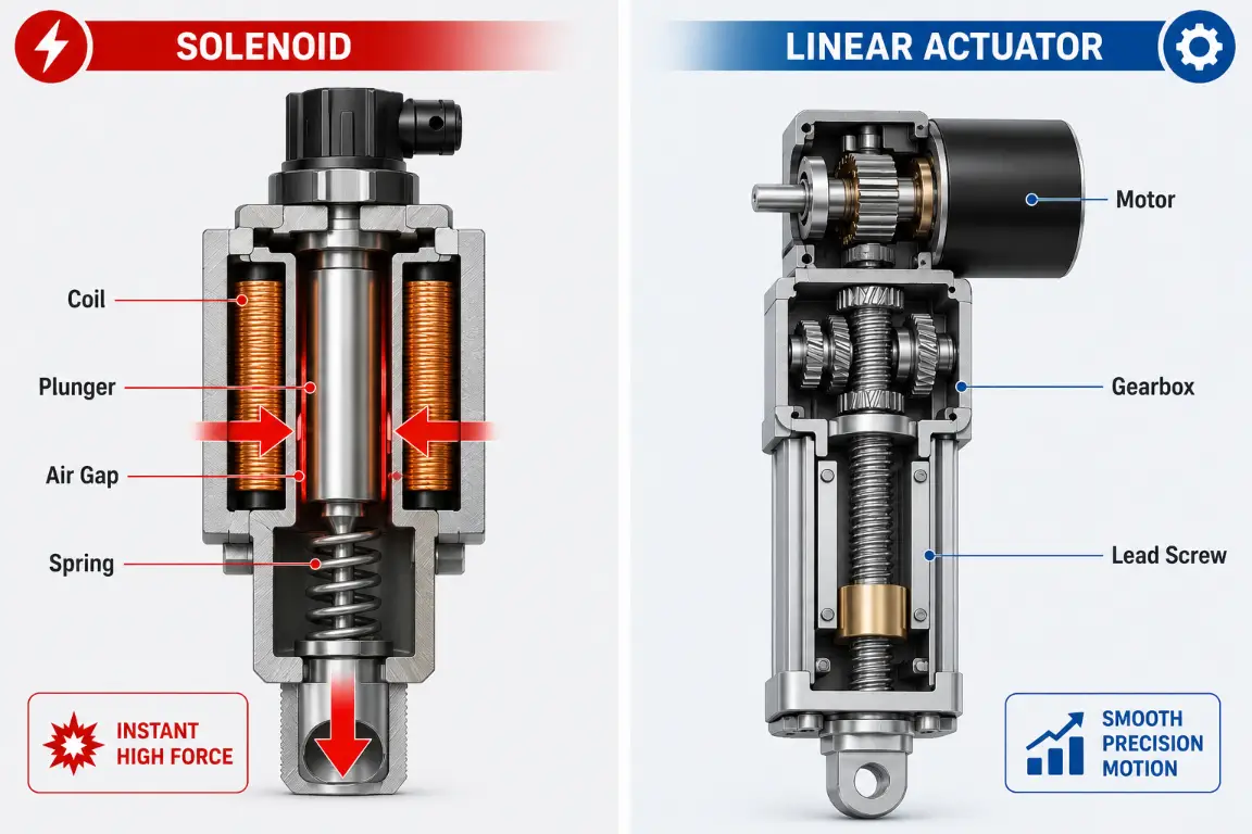
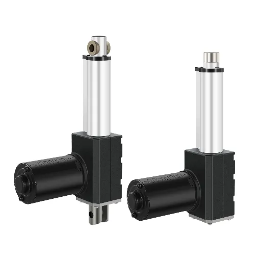
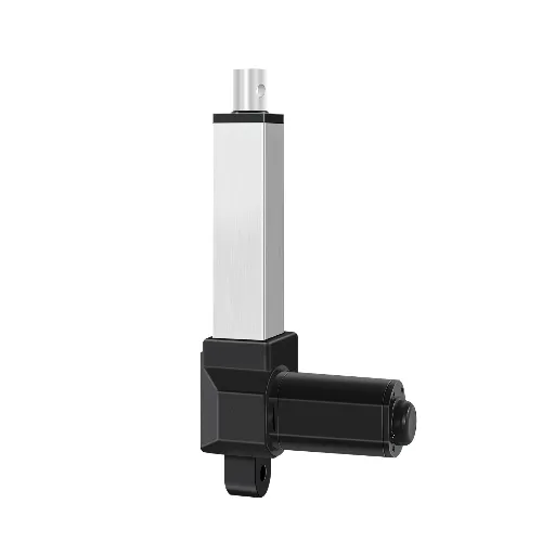
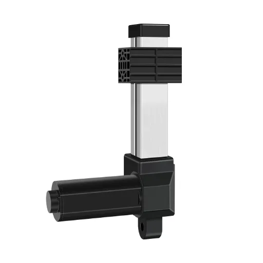
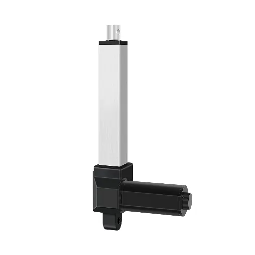
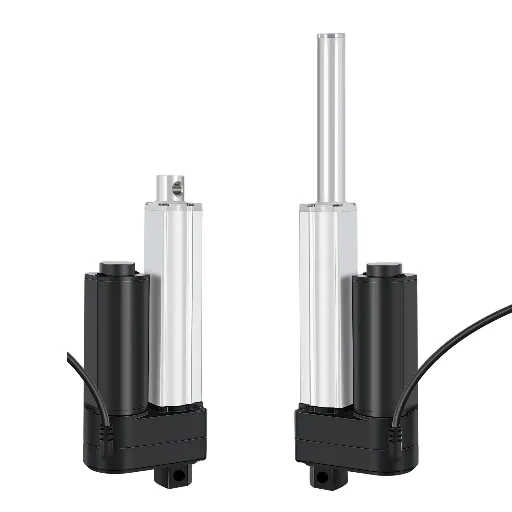
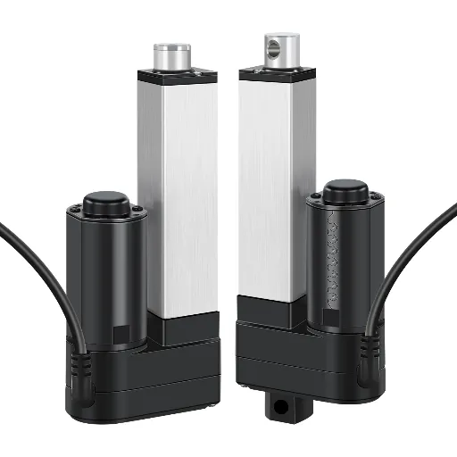
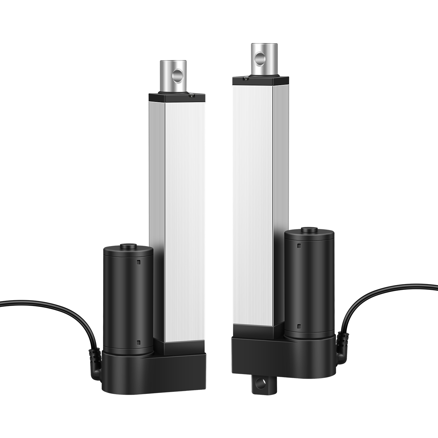
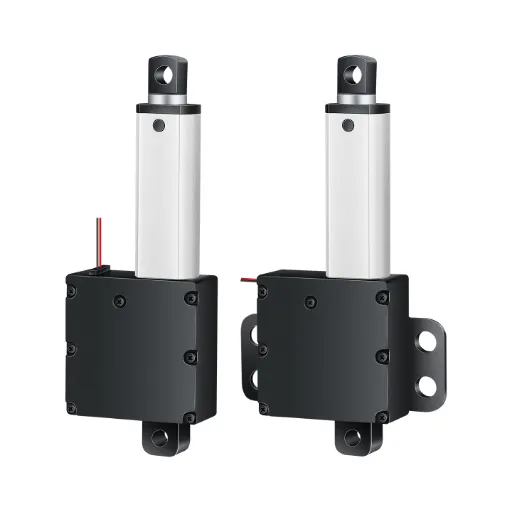
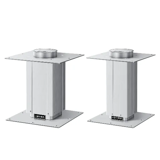
It is precisely due to this that the DIY component approach is being quickly discarded by modern mechanical engineers and procurement experts in favor of the Electric Linear Actuator, an ideal, industrial-quality encapsulation of the entire motion process into a single unit. The rotational electric motor, the gear reduction system and the linear screw mechanism are contained in one ruggedized and pre-aligned protective cylinder, which is an electric actuator.
This dramatically reduces the mechanical complexity and the mechanism design burden for your team. Engineers need not struggle with mechanical tolerances and dust protection measures, but can just define their needed stroke length, speed, and force, and attach a complete, tested product to their machine architecture.
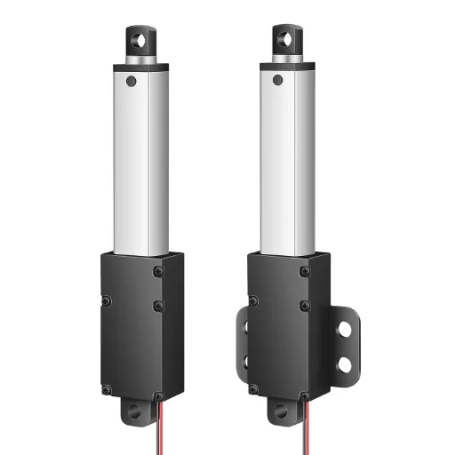
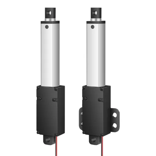
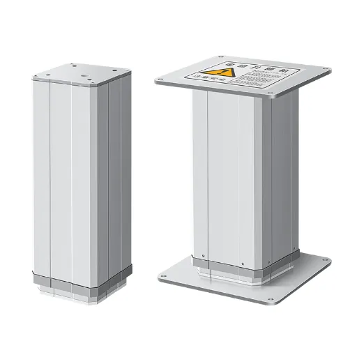
When choosing the linear motion components of your design, partnering with an experienced actuator manufacturer like Hoodland revolutionizes industrial motion control. Their extensive linear actuator lineup, ranging from heavy-duty pushers to a highly compact micro linear actuator, does away with the headaches of assembly of custom components.
The Hoodland Engineering Advantage:
- Unmatched Depth in Customization: Modern designs and modern products from Hoodland provide deep customization. Utilizing their extensive in-house tooling and machining workshops, they do not just sell off-the-shelf standards. Whether you need a highly specific 235mm stroke length, a unique mounting bracket cut to solve a tight clearance issue, or custom wiring harnesses, they deliver true “plug-and-play” solutions tailored to your exact machine design.
- Industrial Muscle Meets Whisper-Quiet Operation: The product line of Hoodland has a very broad range of load. In the case of heavy automation, they provide their IP6000 series with an impressive 6000N (about 600kg) of thrust. Yet, through their precision mold background and highly accurate gear meshing, their precision series maintains a “whisper-quiet” noise level of <50dB. This unique combination of high force and library-level acoustics makes them the premier choice for noise-sensitive medical devices, adjustable office desks, and luxury smart home applications.
- Intelligent Control & Flawless Synchronization: Hoodland actuators are not just raw motors; they are intelligent motion devices. By incorporating built-in Hall sensors or potentiometers, they provide exact position feedback. This allows their proprietary controllers to achieve perfect multi-actuator synchronization, allowing for highly flexible control and executing smooth “Soft Start/Stop” profiles, ensuring that your heavy or delicate payloads are never subjected to sudden, damaging mechanical jerks.
- Proven Reliability & Hardcore Certification: Each and every unit is subjected to a strict 100% quality check and a 2-hour aging test before they are shipped out of the factory. Hoodland has a lifetime of 30,000 cycles, which is quite impressive. In addition to the conventional ISO9001, CE and RoHS certification, the technical moat of Hoodland is also emphasized by their Explosion-proof certification (Ex ib IIA T6 Gb) on some of their models. This demonstrates their superior sealing technology which enables safe and reliable linear movement in highly volatile chemical, oil and mining conditions.
When you combine a Hoodland electric actuator, it is not only that you are buying a mechanical part, but you are buying back hundreds of engineering hours, mechanical alignment assurance, and immediate, internationally recognized industrial compliance to your equipment.
Decision Matrix and FAQ: Selecting the Right Motion Mechanism
In order to simplify your engineering design, the following matrix can be used to compare the core mechanisms of converting rotational to linear motion using common industrial performance measures.
| Mechanism Type | Typical Speed | Precision & Backlash | Max Load Capacity | Stroke Length limits | Maintenance & Protection |
| Slider-Crank | High (Cyclical) | Moderate | Medium | Short (Fixed by crank) | Requires frequent lubrication; hard to seal. |
| Belt Drive | Very High | Low to Moderate | Low to Medium | Very Long (>10m) | Low maintenance; susceptible to dust/debris. |
| Lead Screw | Low to Medium | Moderate (High friction) | Medium | Short to Medium | High wear; requires lubrication; self-locking. |
| Ball Screw | Medium to High | Very High (Zero Backlash) | High | Medium (Prone to whip) | Requires clean environment & regular greasing. |
| Rack & Pinion | High | Moderate to High | Very High | Unlimited | Needs heavy lubrication; open to the environment. |
| Electric Actuator (Hoodland) | Fully Customizable | High (Internal screw) | Very High (up to 6000N) | Fully Customizable | Maintenance-free; High IP ratings (up to IP66); Plug & Play. |
Frequently Asked Questions (FAQ)
Q: What is the main difference between a lead screw and a ball screw?
A: The primary difference is friction. The sliding friction between the thread and the nut is employed in lead screws, which are cheaper and self-locking but less efficient. Recirculating ball bearings (rolling friction) are used in ball screws, and are therefore highly efficient, very precise, and can run with zero backlash, but normally need brakes to support loads in the vertical direction.
Q: Why should I choose an integrated electric actuator over building my own screw-driven system?
A: Building your own system requires calculating complex mechanical alignments, sourcing separate NEMA motors, gears, and screws, and designing custom enclosures to protect against dust and water. Manufacturers such as Hoodland offer integrated actuators which are pre-aligned, fully sealed (high IP rating), tested and save a lot of engineering time and assembly errors.
Q: Can linear actuators be synchronized?
A: Yes. Advanced electric linear actuators equipped with position feedback mechanisms, such as built-in Hall sensors or potentiometers, can communicate with a central controller. This enables several actuators to work in flawless coordination, and this guarantees that big platforms are raised without being bound or twisted.
Q: What does a <50dB noise rating mean for an actuator?
A: A noise level of less than 50 decibels can be said to be “whisper-quiet,” which is approximately the same as the sound of a quiet library or a quiet house in the suburbs. This renders these particular actuators to be suitable in the indoor setting, medical facilities, dental chairs, and ergonomic office furniture where mechanical grinding sounds cannot be tolerated.