Controlled motion is the key component of advanced machinery in the fast-changing environment of modern industrial automation, robotics, and intelligent infrastructure. However, creating accurate, repeatable and strong movement is a complicated engineering problem. If you have ever wondered how a massive hospital bed smoothly adjusts its height with a whisper, how a robotic arm perfectly positions a heavy payload, or how an entire matrix of solar panels flawlessly tracks the sun across the sky, the answer almost universally involves a linear actuator.
For those asking exactly how do linear actuators work, this is a complete engineering manual that will dissect the mechanism of operation of these critical electromechanical parts. We will discuss the internal physical mechanics, compare the core power sources that are ruling the industry, delve into the different drive mechanisms and give you a very practical framework of calculating your load requirements. By the end of this guide, you will have the technical knowledge necessary to select the perfect linear motion solution for your next automation project.
What Is a Linear Actuator and Its Primary Function?
Reduced to its most fundamental engineering definition, a linear actuator is a mechanical or electromechanical device that converts rotational motion into linear movement. Whereas conventional electric motors rotate (rotational motion) in a circle, nearly all industrial, commercial and consumer applications demand that something be pushed, pulled, lifted, lowered or placed in a straight line. The linear actuator serves as the critical bridge between the rotating power source and the physical straight-line displacement required by the machine’s architecture.
The primary function of a linear actuator within industrial automation is to provide precise, controlled, and repeatable directional force. These are the “muscles” of an automated system. Prior to the introduction of dependable linear actuators, most push/pull tasks were performed by manual means or extremely complicated, extremely inefficient mechanical connections. Today, linear actuators solve the basic “literacy” needs of automation: they take an electrical control signal and translate it into a physical action that interacts with the real world.
Moreover, linear actuators are made to maintain positions in a reliable manner once they have reached their target destination. Unlike humans, who experience fatigue, a properly specified linear actuator can hold a heavy static load in a suspended position indefinitely, ensuring safety and structural integrity in critical applications like medical beds or heavy machinery platforms.
How Does a Linear Actuator Work: The Internal Mechanics
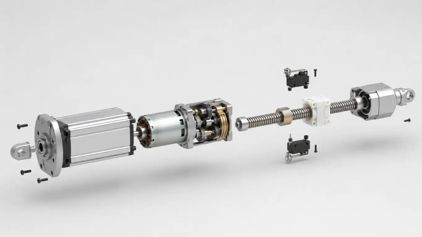
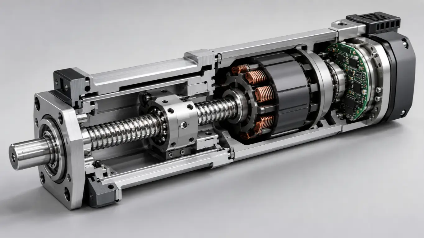
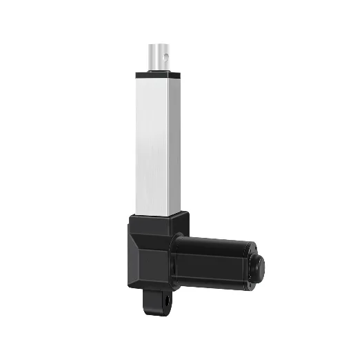
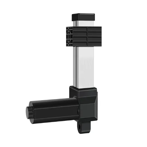
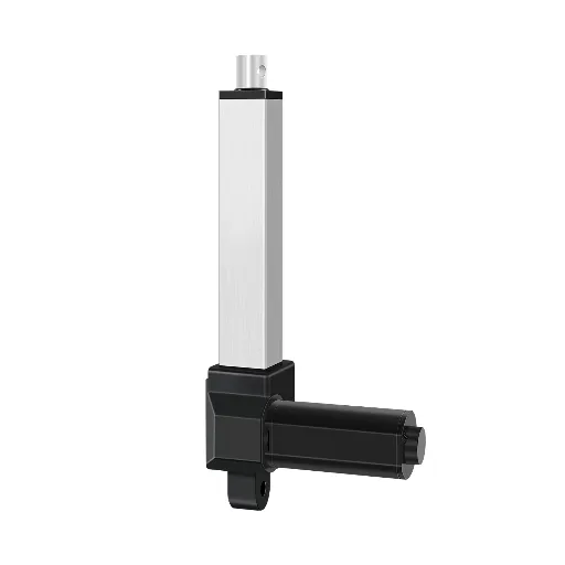
In order to get a real insight into the physics of a linear actuator, we need to open the “black box” and look inside the physical transmission chain. Although the external designs are wildly different depending on the type, load rating and environmental use, the overwhelming majority of standard electromechanical actuators have a common underlying mechanical design. The conversion of energy follows a highly precise, step-by-step path: Motor -> Gearbox -> Lead Screw -> Nut -> Extension Tube.
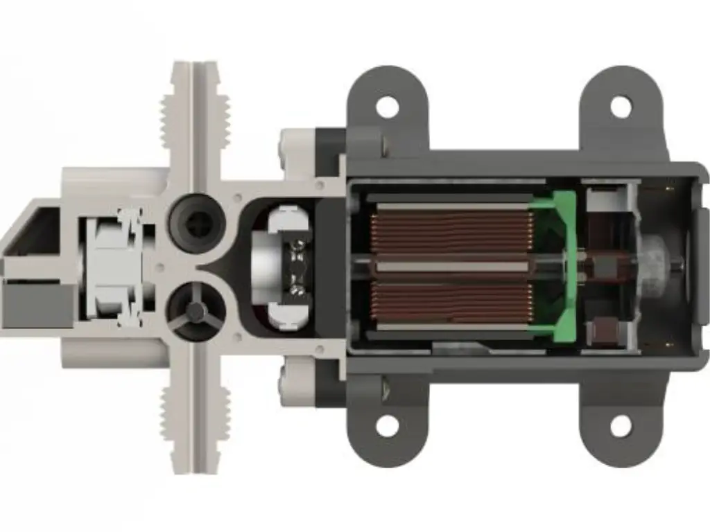
- The Motor (The Power Source)
The mechanical process starts with the electric motor which is usually a DC (Direct Current) motor or one of the common AC motors based on the power needs. When electrical power is applied, the motor generates high-speed rotational motion (measured in RPM) and a specific amount of rotational force (torque). DC motors are very popular in precision applications as the speed can be easily controlled by changing the input voltage.
- The Gearbox (Speed Reduction and Torque Multiplication)
Electric motors typically rotate much too rapidly and produce too little crude torque to be useful in heavy lifting or pushing. Thus, a gearbox is directly connected to the output shaft of the motor. The gearbox is filled with a series of gears (usually spur gears or planetary gear systems) that are intended to significantly slow down the high rotational speed of the motor and at the same time increase the torque many times over. This is a fundamental trade-off in mechanical physics: you sacrifice speed to gain the sheer pushing or pulling power required for the application.
- The Lead Screw (The Conversion Component)
The rotational energy multiplied out of the gearbox is then passed on to a long threaded cylindrical shaft called the lead screw (or drive screw). The lead screw rotates continuously as the gearbox turns, and is held in place by thrust bearings that take the axial loads.
- The Drive Nut and Extension Tube (Creating Linear Motion)
A drive nut is a fine machined nut threaded on the lead screw. This nut is physically attached to the inner extension tube (the visible rod that extends out of the actuator casing). More importantly, the nut is held in place by the outer housing in a mechanical way to prevent it to rotate together with the screw. Because the nut is prevented from spinning, the rotational movement of the threaded screw forces the nut to travel forward or backward along the screw’s threads—much like driving a bolt through a fixed block of wood.
The nut pushes or pulls the extension tube attached to it as it moves up and down the lead screw, producing the final linear motion. Simply reversing the electrical polarity of the motor reverses the rotation of the screw, which in turn retracts the extension tube back into the housing.
Electric vs. Hydraulic vs. Pneumatic Linear Actuators Explained
One of the most important system-level decisions that engineers make when starting an automation project is the selection of the underlying power source of the linear motion. When evaluating the different types of linear actuators, there are three major categories that dominate the industry commonly known as the “Big Three”: Electric, Hydraulic, and Pneumatic. They are based on completely different physical principles and have different benefits.
Below is a comprehensive comparison matrix evaluating these three technologies across five critical engineering dimensions:
| Dimension | Electric Actuators | Hydraulic Actuators | Pneumatic Actuators |
| Power Source | Electricity (Motor & Gearbox) | Pressurized Fluid (Oil) | Pressurized Gas (Air) |
| Thrust / Force | Moderate to High | Extremely High (Heavy Duty) | Low to Moderate |
| Speed & Response | Moderate (Highly Controllable) | Slow to Moderate | Very Fast & Responsive |
| Precision & Control | Exceptional (Sub-millimeter) | Moderate (Prone to drift) | Low (Hard to stop mid-stroke) |
| Cost & Maintenance | Low Maintenance, Higher Initial Cost | High Maintenance (Leaks, pumps), High Cost | Low Component Cost, High Compressor Cost |
Electric Actuators have become the gold standard for most modern automation tasks. Their value is high due to the fact that they are clean (no oil spills), extremely easy to be integrated in digital control systems, and they need practically no maintenance during their life.
Hydraulic Actuators are used in brute-force applications. Since liquids are incompressible, hydraulics are capable of producing impressive levels of force and are therefore the default in construction excavators and heavy metal-forming presses. Nevertheless, they need elaborate infrastructure (pumps, reservoirs, hoses) and are infamous in their untidy fluid spills.
Pneumatic Actuators are best used in areas that need a quick, repetitive movement like in a packaging line or automated sorting system. They are very cost effective in terms of unit cost, but cannot easily stop and maintain an accurate position during the stroke because of the compressibility of compressed air.
Advanced Actuation: Linear Motors & Piezoelectric
Although the mainstream manufacturing is dominated by the “Big Three,” the advanced actuation technologies are needed to push the limits of high-tech engineering. The specialized actuators are used in cases where the normal mechanical linkages are just not able to achieve the speed or precision specifications.
Linear Motors
Suppose you have a typical rotary electric motor, and slice it along its radius and roll it out flat. This is essentially a linear motor. The electromagnetic force does not act on a rotor, but directly on a straight magnetic track, a “forcer.” Linear motors have no gears, lead screws, or mechanical contact points, which means that they have staggering speeds, extremely high acceleration, and zero mechanical backlash. They are heavily utilized in semiconductor manufacturing, high-end CNC machining, and maglev transportation.
Piezoelectric Actuators
The piezoelectric technology is based on a peculiar physical effect: some ceramics and crystals alter their physical form (expand or shrink) when an electrical voltage is applied to them. While the total travel distance (stroke) of a piezoelectric actuator is microscopically small—often measured in micrometers—the precision is absolute, operating at the nanometer level. They boast microsecond response times and are crucial for optical lens micro-adjustments, electron microscope stages, and precision fluid dispensing valves.
Voice Coil Actuators
Working on the same principle as an audio speaker, voice coils utilize a current carrying coil installed within a permanent magnetic field. They provide high frequency oscillation and very fine force control, which is suitable in medical ventilators and sensitive testing devices.
Common Drive Mechanisms: Lead Screws, Ball Screws, and Belts
In the case of electric linear actuators, the efficiency, life cycle, and load capacity of the device is determined by the process of converting rotary motion into linear motion. Mechanical drive systems are complex systems that require understanding to be specified correctly.
Lead Screws (Acme Screws)
The most common and economical drive mechanism is the lead screw which is the Acme thread profile. It is made of a threaded steel shaft and a mating nut (usually of bronze or special polymer). As the screw turns, the high sliding friction between the threads moves the nut.
- Key Advantage: Self-locking. The friction is high such that the actuator will not back-drive when power is cut under load. This is a very important safety aspect of lifting applications.
- Drawback: Low mechanical efficiency (typically 30% to 40%). The friction between the sliding causes heat, which restricts the speed and the duty cycle.
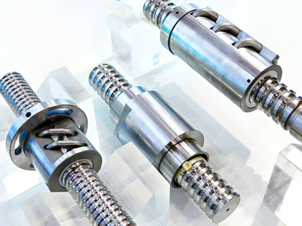
Ball Screws
Lead screws are an important engineering improvement compared to ball screws. Instead of sliding friction, a ball screw utilizes a recirculating pathway of hardened steel ball bearings that roll between the screw shaft and the nut.
- Key Advantage: High efficiency (usually more than 90%), much greater life and continuous operation at high speeds without overheating.
- Drawback: They are not self-locking. The friction is so low that a heavy stationary load may cause the screw to rotate backward when power is switched off. Ball screw actuators almost always require an integrated electromechanical brake to hold loads safely.
Belt-Driven Systems
The motor does not have a screw, but rather drives a high tension, steel-reinforced timing belt attached to a carriage.
- Key Advantage: Belt drives excel in high-speed, long-stroke applications where a screw would suffer from “whip” (dangerous vibrations at high RPMs over long distances).
- Drawback: They are typically incapable of dealing with the large axial pushing forces that screw-driven actuators can, and the belts need to be periodically tensioned.
Rack and Pinion
A rotational gear (pinion) engages with a linear gear bar (rack). This is a very rigid mechanism and is very effective when there are many actuation points that must be synchronized mechanically over long distances, as is common in heavy gantry systems.
How to Calculate Load and Size the Right Actuator
Choosing an actuator by a mere “guess” will most certainly result in an untimely mechanical breakdown or a scalded motor. To select the right linear actuator, a strict assessment of the loads that it will face and the frequency of its operation is necessary.
1. Calculating Dynamic Load (Thrust)
Dynamic Load is the push or pull force that the actuator has to apply when it is in motion. When you are pushing a block horizontally, you have to compute the friction. If you are lifting a mass vertically against gravity, the force required can be calculated using standard Newtonian physics:
Force (F) = mass (m) x gravity (g)
Where F is force in Newtons, m is the mass in kilograms, and g is the acceleration due to gravity (9.81 m/s²). Always add a safety factor of at least 20% to 25% to your calculated dynamic load to account for unexpected friction or temporary binding.
2. Calculating Static Load (Holding Force)
The Static Load is the maximum amount of weight or force the actuator can safely hold in a fixed, unmoving position without the internal gears stripping or the screw back-driving. In many architectural or medical applications, the required static load rating is actually much higher than the dynamic load rating.
3. Understanding Duty Cycle
The most frequent cause of failure of electric actuators is perhaps overloading their stated Duty Cycle. The ratio of operating time to resting time is called duty cycle and is expressed as a percentage. It determines the duration of the motor running time before it has to cool down to avoid melting its internal insulation.
The formula is: Duty Cycle = [Time On / (Time On + Time Off)] x 100%
Assuming that an actuator has a 25% duty cycle rating, and that it requires 15 seconds to fully extend, then it requires 45 seconds to be able to be operated again. A ball screw actuator or a motor with better heat dissipation should be specified in case your application needs a high duty cycle.
Essential Sizing Checklist:
- What is the maximum Dynamic Load?
- What is the maximum Static Load?
- What is the required Stroke Length (distance traveled)?
- What is the desired operating Speed (under load)?
- What is the operational Duty Cycle?
- Are there any side-loads (radial forces)? Note: Actuators are designed for axial loads only; side-loads will bend the extension tube.
Control Systems, Limit Switches, and Position Feedback Sensors
An actuator is only as useful as the “brain” controlling it. The control systems control safety, determine speed and give the accurate positional awareness required in complex automation.
Limit Switches (The Physical Safety Net)
Built-in limit switches are non-negotiable safety features for most electromechanical actuators. These electro-mechanical switches are physically cut by the electrical current to the motor at the extreme ends of the actuator stroke (fully extended and fully retracted) as the nut reaches the end of the line. Without limit switches, the motor would continue attempting to turn against a physical barrier, resulting in a rapid spike in current that would instantly melt the motor windings or shatter the internal gearbox.
Basic Control: DC Reversing and PWM
At the most basic level, a DC linear actuator is controlled by a Double-Pole Double-Throw (DPDT) switch or a relay circuit that simply flips the polarity of the DC voltage to change direction. Pulse Width Modulation (PWM) is used by engineers to provide more advanced control. By rapidly turning the power on and off thousands of times per second, a motor controller can smoothly ramp up the actuator’s speed (Soft Start) and gently decelerate it (Soft Stop), preventing violent mechanical jerks that could damage delicate payloads.
Position Feedback: Giving the Actuator a “Memory”
Standard actuators are “blind”—you apply power, and they move. But what if you need the actuator to stop exactly at 115mm, or synchronize two actuators to lift a platform perfectly level? This precise positioning requires position feedback sensors:
- Hall Effect Sensors: These use magnets mounted on the motor shaft to generate electrical pulses as the motor spins. These pulses are counted by the controller to know the precise distance that the actuator has covered.
- Optical Encoders: Utilizing a light source and a slotted disk, encoders provide incredibly high-resolution feedback for CNC-level precision.
- Potentiometers: These give an analog signal of voltage, which varies linearly with the extension of the actuator, and which gives absolute position information (even when power is cut off, the system will remember its precise position).
PLC Integration
In large-scale industrial settings, the feedback data from Hall sensors or encoders is fed directly into a Programmable Logic Controller (PLC). The PLC processes this data in real-time, allowing the linear actuator to interact seamlessly with other automated machinery, timing gates, and robotic arms along an assembly line.
Industrial Applications and Common Automation Use Cases
Due to their ability to provide such a wide range of control over force and movement, linear actuators are used in practically all industrial machinery and sectors of the contemporary B2B economy.
Renewable Energy: Solar Tracking Systems
In the renewable energy sector, heavy-duty actuators are the mechanical backbone of single and dual-axis solar tracking systems. Rather than remaining static, these systems rely on high-force actuators to continuously tilt massive arrays of photovoltaic panels, following the sun’s trajectory to maximize energy capture by up to 30%. Since they are used in severe outdoor conditions, these actuators are specifically designed with high Ingress Protection (IP) ratings (e.g. IP66 or IP69K) to survive under extreme UV conditions, heavy rain, and enormous wind shear loads without mechanical drift.
Precision Agriculture and Heavy Farming Machinery
Similarly, modern precision agriculture heavily relies on rugged linear actuators. They are fitted to combine harvesters to remotely operate heavy grain tank covers, rotor vanes and threshing mechanisms directly through the driver cabin. They are used in smart farming systems to give the precise micro-adjustments needed in automated fertilizer flow valves and seed drills. More importantly, electric linear actuators are fast replacing the conventional hydraulic cylinders in agriculture since there is no chance of hydraulic fluid leakage, which can disastrously pollute the soil and crops.
Packaging, Logistics, and Rigid Container Machinery
Speed and absolute repeatability are the most important in the world of packaging and logistics, which is fast-paced. High-speed belt-driven actuators are often utilized in sorting facilities to quickly divert heavy boxes on conveyor belts. Nevertheless, automated fluid dispensing and high-speed rigid packaging machinery applications are the most challenging. For advanced canning lines and rigid container packaging, precision screw-driven actuators are absolutely critical. They provide the exact thrust force and millimeter-level positioning required for precise volumetric filling, capping, and tight seaming operations. Unlike flexible packaging, rigid packaging machinery requires actuators that can deliver immense, repetitive downward forces to seal containers perfectly without crushing the cans or bottles themselves, making programmable electric actuators indispensable for maintaining consistent production quality.
The Medical Sphere: Hospital Beds and Surgical Tables
Reliability and comfort to the patient are the end goals in the medical field. High-end hospital beds, bariatric chairs, and surgical tables use a system of several synchronized actuators to adjust the position of the head, foot and total height silently and smoothly. Such complicated kinematics demand accurate position feedback (such as Hall sensors) combined with a central control box to make sure that the bed lifts up exactly even without shaking the patient. Moreover, actuators in this industry should be highly medically certified, have whisper quiet noise levels to not disrupt patient recovery, and have critical safety overrides, including a manual quick-release system to flatten the bed immediately in case of emergency CPR.

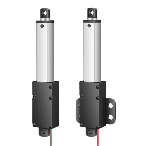
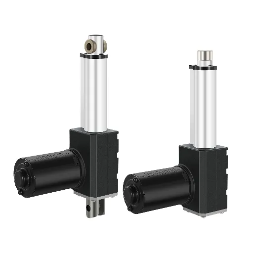
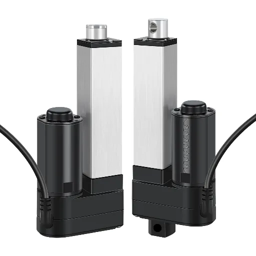
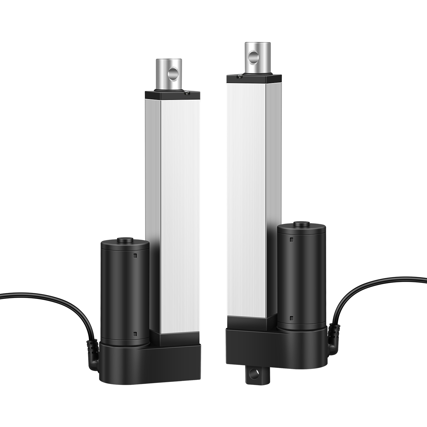
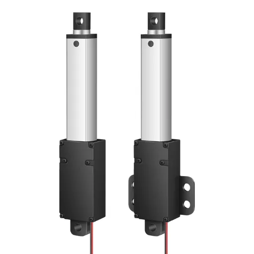
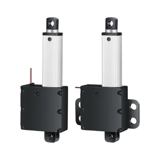
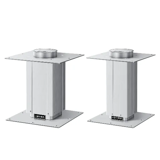
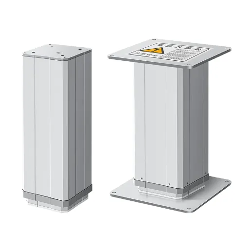
Compact & Custom Electric Actuators by Hoodland
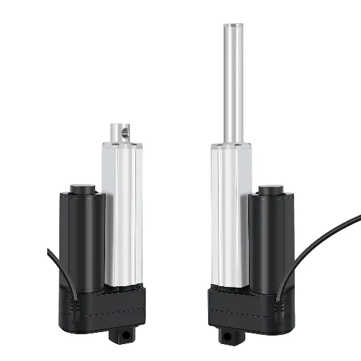
Whereas heavy industry is controlled by massive hydraulic cylinders, there is a fast-growing need to control fine movements in limited areas. For smart home integrations (such as automated range hoods, concealed TV lifts, and automated cabinetry), cutting-edge robotics, and medical applications where installation space is strictly limited, a bulky standard actuator simply will not fit. In these scenarios, compact DC electric actuators are the ultimate solution.
Hoodland focuses on research, development and production of high quality DC 6V/12V/24V micro linear actuators and heavy duty lifting columns that are specifically designed to meet these contemporary challenges. Using a deep engineering DNA that is based on our 1989 experience in mold manufacturing, Hoodland has perfected the art of putting enormous power into very small form factors.
Our products solve the industry’s most frustrating pain points. For environments where noise is a critical concern—such as hospital wards or premium residential interiors—our actuators feature whisper-quiet operation at <50dB, achieved through high-precision gear meshing and bespoke motor designs. Furthermore, industrial-grade reliability is engineered into every unit; our actuators are designed for an impressive 30,000-cycle lifespan, with every single unit undergoing a rigorous 2-hour aging test and 100% full inspection before shipment.
In addition to conventional hardware, Hoodland products are fully loaded with built-in limit switches and various electrical protection (over-current, over-voltage, and short-circuit), and can easily be integrated with wireless control through our own control systems. Our factory has ISO9001, CE, RoHS and rare Ex explosion-proof certifications, so compliance is ensured.
We are not just selling off-the-shelf parts because we are an experienced source manufacturer with in-house machining capabilities. We offer highly flexible stroke customization from 10mm to 200mm+ and beyond, tailored exactly to your chassis.
[Consult Hoodland Engineers for Custom Actuators and Technical Support Today]
Common Troubleshooting Tips and Essential Maintenance Practices
Even the highest quality linear actuators require proper integration and occasional troubleshooting. Neglecting the warning signs may cause disastrous mechanical breakdown. These are some of the most important maintenance practices and remedies to the most prevalent engineering failures.
- The Actuator is Binding or Stuck Mid-Stroke
If the actuator stalls before reaching its limit switches, the most common culprit is a side-load (radial load). Actuators are only developed to handle push/pull axial forces. When the mounting brackets are not aligned even a bit, the extension tube will bend and the internal nut will be caught by the lead screw.
Solution: Disconnect the actuator from the load and run it freely. If it moves smoothly, your mounting geometry is misaligned. Use spherical rod end bearings to absorb minor structural misalignments.
- Motor Overheating and Thermal Shutdown
When the actuator casing is so hot that it is painful to touch or no longer responds at all, then you have probably overloaded it with its rated Duty Cycle. Forcing a 10% duty cycle actuator to run continuously will melt the internal wiring insulation.
Solution: Either decrease the frequency of operation, reduce the applied weight, or upgrade to a continuous-duty ball screw actuator with superior thermal dissipation.
- Clicking Noises and Gear Stripping
When there is a loud clicking or grinding sound during load, it means that the internal gearbox is malfunctioning or the torque limit has been surpassed. This often happens if the actuator is subjected to sudden shock loads (like dropping a heavy weight onto the extended rod).
Solution: Ensure your system utilizes soft-start PWM control to prevent jerk. In case the gears are stripped, the actuator should be changed.
- Essential Lubrication Practices
For lead screw actuators, lubrication is the lifeblood of the mechanism. If the actuator begins to squeak or draw higher electrical current than usual (which can be monitored via a PLC), the sliding friction has increased. Solution: Every 6 to 12 months (depending on the environment), the extension tube should be cleaned of dust and debris, and a high-quality lithium-based or PTFE (Teflon) grease should be applied to the internal screw threads to maintain optimal mechanical efficiency and prevent premature wear.