
In the complex and risk-stake electrical engineering environment, the protection of systems against abnormal electrical operation is not only a best practice issue, but a mandatory regulatory provision and a cornerstone of system design. Whether you are engineering a high-voltage industrial distribution panel, designing a compact printed circuit board (PCB) for consumer electronics, or architecting the power matrix for a next-generation electric vehicle (EV) charging station, understanding the precise mechanics of overcurrent is non-negotiable.
This comprehensive guide delves deep into the physics, component selection, technical sizing, and regulatory standards surrounding overcurrent protection. This article will provide engineers, system integrators, and technical procurement specialists with the knowledge necessary to select the specific Overcurrent Protection Device (OCPD) to be used in any particular application by deconstructing the basic differences between the different fault conditions and dissecting the advanced protection devices currently available.
What Is Overcurrent Protection and Why Is It Essential?
At its core, overcurrent protection is the engineered safeguard against any current that exceeds the rated capacity of equipment or the ampacity of a conductor. When an electrical circuit experiences a current draw higher than its designed operational limits, the immediate consequence is a rapid escalation in temperature and massive electrodynamic stress. In such cases, the important sentinels are Overcurrent Protection Devices (OCPDs) which are set to automatically cut off the flow of electricity before it can cause irreparable equipment damage.
In order to see why this is necessary, it is necessary to examine the physical principles of electrical circuits. The first law of Joule states that the amount of heating power produced by an electrical conductor is proportional to the square of the product of the current and the resistance. Because the current factor is squared, even a marginal increase in current leads to an exponential surge in thermal energy. If left unchecked, this thermal accumulation will rapidly degrade wire insulation, melt solder joints, destroy sensitive semiconductor junctions, and ultimately ignite surrounding combustible materials.
Beyond thermal destruction, severe overcurrent events generate immense magnetic forces. The fault current electrodynamic force between two parallel conductors can be so great that it physically violently bends copper busbars, breaks insulators, and blows enclosures open. Thus, an overcurrent protection device is not simply ensuring that a wire does not get too hot, it is ensuring that mechanical explosions and the risk of electrical fires in facilities are prevented.
The essential nature of overcurrent protection is further underscored by the lifecycle of capital equipment. Transformers, industrial motors, and costly automated manufacturing arrays are highly dependent on steady power. A poorly sized or faulty OCPD may cause “nuisance tripping,” which is expensive to operate, or worse, not to trip at all, causing the loss of multimillion-dollar equipment. As a result, overcurrent protection is the absolute minimum of operational reliability, electrical safety of personnel, and the life of assets.
3 Main Overcurrent Types: Overload, Short Circuit, Ground Fault
The most widespread myth among the beginner designers is the confusion of the terms “overload” and “short circuit.” But as an engineering matter, they are completely different physical phenomena that need different protection measures. Understanding these three primary fault conditions is the first step in properly sizing an OCPD.
- Overload
An overload is a condition when equipment is operating with a current that is greater than the normal, full-load current rating, yet the current is contained within the normal current carrying path. This is normally a gradual, progressive thermal process. As an illustration, when a conveyor belt motor is mechanically locked or compelled to transport a heavier load than the design requirement, it will draw an excessive current flow through the grid to produce the required torque. The overloads typically vary between 135% and 600% percent of the rated continuous current of the circuit. Since the accumulation of heat is slow, overload protection devices have an “inverse-time” characteristic, that is, they permit small overloads to last longer (to accommodate harmless temporary overloads, such as the startup of a motor) but clear sooner as the overload size increases.
- Short Circuit
A short circuit is a violent, instantaneous event where an unintended, near-zero resistance path is established between two conductors of different potentials (e.g., Line to Line, or Line to Neutral). Because the resistance drops dramatically, Ohm’s Law dictates that the current will spike to astronomical levels, often reaching thousands or tens of thousands of amperes within a fraction of a millisecond. This huge rush does not go through the usual load. The short circuit energy will lead to instant arcing, metal vaporization, and possible explosive explosions. Protection against this severe overcurrent condition must be virtually instantaneous, relying on magnetic or fast-acting solid-state mechanisms to clear the fault before the peak let-through energy destroys the infrastructure.
- Ground Fault
A ground fault is a particular form of short circuit in which the unwanted conductive path is between an ungrounded conductor and the earth/ground (e.g. the metal chassis of a machine). Ground faults are particularly insidious because they can involve very low fault currents if the ground path has high impedance. While a 2-ampere ground fault might not trigger a standard 20A circuit breaker, it is more than enough to cause lethal electrocution to a human operator touching the energized chassis. Hence, specialized ground-fault protection is based on the ability to sense imbalances between outgoing and returning current, and not only on the absolute current magnitude.
Comparative Analysis of Overcurrent Types
| Characteristic | Overload | Short Circuit | Ground Fault |
| Current Multiple | 1.3x to 6x of rated current | 10x to 1000x+ of rated current | Can be very low (mA) to very high (kA) |
| Trigger Condition | Mechanical binding, excessive load, adding too many devices to a circuit | Insulation failure, physical bridging of phase conductors, tool drops across busbars | Insulation breakdown, moisture ingress, compromised grounding path connecting phase to chassis |
| Duration / Time to Trip | Seconds to Minutes (Inverse-time delay) | Milliseconds (≤ 10ms – 20ms typically) | Milliseconds to Seconds (Depends on life-safety vs. equipment protection thresholds) |
| Potential Hazards | Gradual insulation degradation, eventual thermal fire, reduced equipment lifespan | Arc flash, explosive physical destruction, catastrophic equipment vaporization | Lethal electrical shock to personnel, localized burning at the fault point |
Main Types of Overcurrent Protection Devices (OCPDs) Explained
Overcurrent protection devices are not one-size-fits-all. From towering distribution switchgear to compact printed circuit boards (PCBs), selecting the correct OCPD requires a delicate balancing act. Engineers must weigh the Response Time (how fast the device clears the fault), the Interrupting Rating (the maximum fault current the device can safely interrupt without destroying itself), and Resettability (whether the device must be replaced after a fault or can simply be reset).
Traditional Protection: Fuses and Circuit Breakers
- Fuses
Fuses are the oldest, yet still most reliable, form of overcurrent protection. They operate as sacrificial devices. Inside the fuse body lies a precise metallic element (often silver or copper alloy) surrounded by an arc-quenching medium like silica sand. When exposed to excessive current, the Joule heating melts the element, breaking the circuit.
Fuses are defined by their incredible Interrupting Ratings (often capable of safely stopping 200kA to 300kA of short-circuit current) and their ampere-squared seconds clearing energy, which measures the thermal energy allowed to pass through during a fault. Current-limiting fuses respond very fast, and may melt and clear a disastrous short circuit in a half-cycle of alternating current (less than 4 milliseconds). The main disadvantage is that a fuse once blown is gone, and has to be replaced physically, which may cause a long downtime in case the spares are not easily accessible.
- Circuit Breakers
Unlike fuses, circuit breakers are resettable mechanical switches. The Thermal-Magnetic circuit breaker is the most common type that is used in industry and commerce. These devices use two different trip mechanisms to deal with the overloads and short circuits.
For overload protection, they utilize a bimetallic strip—two different metals fused together that expand at different rates when heated by overcurrent. This uneven expansion causes the strip to bend, eventually tripping the latching mechanism after a set delay. They use a magnetic solenoid to provide short circuit protection. In the case of a large short-circuit spike, the surge causes a strong electromagnetic field in the coil, and an armature is instantly drawn by it to cause the breaker to open in 10 to 20 milliseconds. While highly convenient due to their resettability, standard mechanical breakers generally have lower maximum interrupting ratings compared to high-tier industrial fuses and are physically bulkier.
Solid-State Solutions: eFuses and PTCs
- eFuses (Electronic Fuses)
As electronics have become denser and more voltage-sensitive, traditional mechanical protection is often too slow. eFuses are silicon-based integrated circuits that utilize an internal power MOSFET to actively manage and restrict current flow. They do not rely on melting metal or bending bimetal strips.
Because they are governed by semiconductor logic, eFuses offer response times in the microsecond (µs) or even nanosecond range. They can limit current instantaneously to protect sensitive DSPs or microprocessors. Furthermore, eFuses often integrate additional features such as Under-Voltage Lockout (UVLO), overvoltage clamping, and slew rate control to prevent inrush currents during “hot-swap” operations in data center servers.
- PTCs (Polymeric Positive Temperature Coefficient Devices)
Commonly known as resettable fuses, PTCs are ubiquitous in consumer electronics, USB ports, and automotive wire harnesses. They consist of a specialized conductive polymer matrix. When operating under normal conditions, the polymer is tightly packed, which has very low resistance. Nevertheless, as the temperature of the component increases due to an overcurrent event, the polymer experiences a phase change, and it expands at a high rate. This expansion breaks the conductive paths, causing the resistance to spike exponentially (tripping the device and reducing current to a safe trickle). Once the power is removed and the device cools, it automatically resets to its low-resistance state. While incredibly convenient, PTCs have slower response times than eFuses and can experience “resistance drift” (permanent slight increases in baseline resistance) after multiple trip events.
Industrial Grid Protection: Overcurrent Relays
- Overcurrent Relays
In medium and high-voltage distribution networks, the logic of fault detection is separated from the physical mechanism of circuit interruption. Overcurrent relays act as the intelligent “brain” of the grid protection scheme. They do not interrupt the main power themselves; instead, they continuously monitor the line current via Current Transformers (CTs).
When an overcurrent is detected, the relay calculates the severity and timing based on its programming and sends a low-voltage trip signal to a massive Air Circuit Breaker (ACB) or Vacuum Circuit Breaker (VCB) to isolate the fault. These systems rely heavily on standardized ANSI device numbers: ANSI 50 represents instantaneous overcurrent protection, while ANSI 51 denotes time-overcurrent protection. The relays of the modern microprocessor type enable the engineer to program very complex trip curves, including Definite Time or Inverse Definite Minimum Time (IDMT) characteristics, to provide absolute accuracy in the coordination of multiple protection zones in a complete power plant or manufacturing facility.
How to Select the Right OCPD for Your Application
The specification of the right overcurrent protection device is a strict mathematical and analytical procedure. It is a risky oversight to guess or merely match the ampicity of a wire. Engineers must strictly follow sizing guidelines and deeply analyze transient system behaviors to ensure safety without causing nuisance tripping.
The 125% Sizing Rule
As a baseline, electrical codes like the NEC mandate that an OCPD must be sized to handle 100% of the non-continuous load of the electrical equipment plus 125% of the continuous load (any load operating for 3 hours or more). The formula is generally expressed as:
I_OCPD = (125% × I_Continuous) + (100% × I_Non-Continuous)
For instance, if a commercial lighting panel draws 40 Amps continuously, the breaker must be sized at a minimum of 50 Amps (40A × 1.25). This prevents the breaker’s internal thermal mechanisms from deteriorating under constant, near-limit heat generation.
Decoding Time-Current Curves (TCC)
To truly select the right device, engineers must master the Time-Current Curve (TCC). A TCC is a logarithmic graph where the X-axis represents current (in Amperes or multiples of rated current) and the Y-axis represents the time it takes for the device to trip (in seconds).
The TCC is important when sizing an OCPD of an electric motor. Motors need a huge inrush current to begin rotating, sometimes known as Locked Rotor Amps (LRA) and may be 6 to 8 times the normal Full Load Amps (FLA) briefly. If you choose a breaker with a “fast” trip curve, the motor’s startup surge will intersect the breaker’s trip zone, causing a nuisance trip every time the machine is turned on. Using the interpretation of the TCC, you are able to choose a “motor-circuit protector” that has a delayed thermal characteristic that will safely ride the 5-second inrush, but will still aggressively trip in the event of a real short circuit.

Essential Selection Checklist
When sourcing an OCPD, strictly evaluate these technical parameters:
- Voltage Rating: The OCPD’s voltage rating must be equal to or greater than the system voltage. A breaker rated for 240V AC will explosively fail if tasked with interrupting a 480V AC fault, as the internal gap is not wide enough to extinguish the high-voltage arc.
- Ampere Rating (Continuous Current): The maximum current the device can carry continuously without tripping, typically governed by the 125% rule mentioned above.
- Interrupting Rating (AIC – Amps Interrupting Capacity): This is, perhaps, the most important safety measure. When the transformer of a facility is capable of delivering 50,000 Amps in case of a dead short, the AIC of the breaker must be strictly above 50kA. When a 10kA AIC breaker tries to clear a 50kA fault, the casing will break, not preventing the current, and leaving a deadly shrapnel and arc-flash threat.
- Environmental Factors: Consider ambient conditions and temperature derating. A thermal breaker calibrated for 40°C will trip at lower currents if installed in a sweltering 60°C boiler room.
Key Electrical Standards and NEC Compliance for OCPDs
Electrical engineering is all about compliance. A poorly certified OCPD is a liability that will not pass the municipal inspections and insurance policies will be canceled. The regulatory environment is crucial to international equipment design.
NEC Article 240 (National Electrical Code)
The National Electrical Code (NFPA 70), in particular, Article 240: Overcurrent Protection, is a hotly contested regulator of sizing and application of overcurrent protection in North America. The basic principle of Article 240 is that equipment and conductors should be guarded at the point of supply. It clearly details the method of calculating protection of special cases, such as the complicated “Tap Rules” (e.g., the 10-foot and 25-foot tap rules), where smaller conductors can be tapped off larger feeder breakers under very stringent length, enclosure, and ampacity limitations without an extra breaker at the tap point.
UL 489 vs. UL 248 vs. UL 1077
Underwriters Laboratories (UL) determines the high standards of testing that devices have to meet in order to be installed.
- UL 489 (Molded-Case Circuit Breakers): This standard defines the strict guidelines of protection of branch circuits. A UL 489 breaker should be capable of interrupting the huge short-circuit currents available on the utility, and should be able to endure ferocious endurance tests.
- UL 248 (Low-Voltage Fuses): This multi-part standard covers everything from fast-acting Class J fuses used in motor controllers to massive Class L fuses used in main switchboards, ensuring specific let-through energy limits are maintained.
- UL 1077 (Supplementary Protectors): It is critical to note that UL 1077 devices look identical to UL 489 breakers but are not allowed to be used as primary branch protection. They are strictly “supplementary” and must be backed up by a UL 489 device or fuse. Misapplying a UL 1077 device is a common and dangerous code violation.
IEC Standards for Global Markets
In the case of international projects, the standards are established by the International Electrotechnical Commission (IEC). The most important standard of industrial low-voltage circuit breakers is IEC 60947-2, which pays much attention to the operational performance in extreme short-circuit conditions (defining such parameters as the ultimate short-circuit breaking capacity and the service short-circuit breaking capacity). On the other hand, IEC 60898 regulates circuit breakers intended to be used in domestic and other similar applications, where uninstructed operation needs an alternative safety test method.
DC Overcurrent Protection for EV Charging and Industrial Systems
While AC (Alternating Current) overcurrent protection has been perfected over a century, the explosive growth of renewable energy and electric vehicles has violently shifted the focus toward DC (Direct Current) protection. DC overcurrent protection presents fundamentally superior engineering challenges compared to AC.
In an AC circuit, the voltage naturally crosses zero 120 times per second (in a 60Hz system). When a mechanical breaker opens during an AC fault, the resulting electrical arc is naturally extinguished during one of these “zero-crossings.” DC power, however, is a continuous, unyielding flow. When a breaker opens on a short circuit in 1000 V DC, the arc of the arc will not extinguish itself, but will violently maintain itself, burning the contacts and jumping across the air gap.
The EV Charging Challenge
Modern EV fast-charging infrastructures, governed by protocols like OCPP (Open Charge Point Protocol) and utilizing hardware standards such as CCS (Combined Charging System) or NACS (North American Charging Standard), deal with enormous DC loads. To drive 350kW to 500kW into a vehicle battery, it takes huge voltages (up to 1000 V DC) and hundreds of amps.
These installations need extremely specialized DC contactors in combination with sophisticated pyrotechnic fuses (pyro-fuses) to protect them. When a catastrophic fault occurs in an EV charging matrix, the vehicle’s telemetry or the charger’s controller fires a small explosive charge inside the pyro-fuse, physically severing the busbar in less than 1 millisecond. This is an incredibly fast break that is the only means of avoiding a dead-short that would transform the charging cable and the lithium-ion battery in the vehicle into an uncontrolled thermal runaway event.

Solar PV and Battery Energy Storage Systems (BESS)
Similarly, commercial solar photovoltaic arrays and massive battery storage farms require precise DC overcurrent strategies. The solar panels are unique in the sense that the short-circuit current is slightly higher than the operating current. Therefore, specialized “PV fuses” (designed to interrupt low-level DC faults without relying on massive surges) and bidirectional DC breakers must be strategically deployed in combiner boxes to prevent reverse-current feeding, where healthy panels dump their energy into a shaded or shorted adjacent panel string.
Sourcing Reliable Overcurrent Protection Solutions with Hoodland
When designing complex industrial power matrices, highly automated medical equipment, or high-demand setups like adjustable smart home and commercial environments, relying on generic protection devices or poorly integrated motors introduces severe compliance and safety risks. Precise current coordination and intelligent fault clearing are non-negotiable to prevent motor burnout, mechanical damage, or electrical hazards.
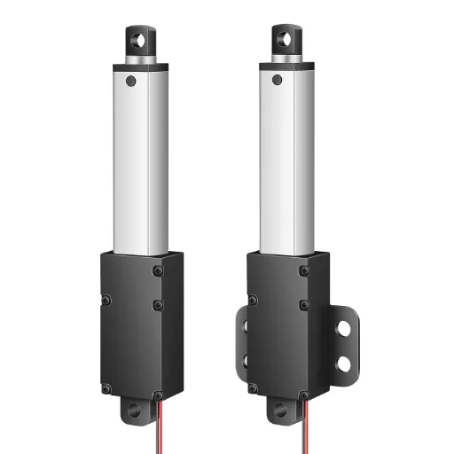
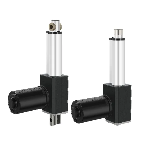
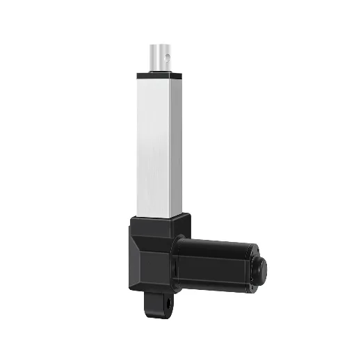
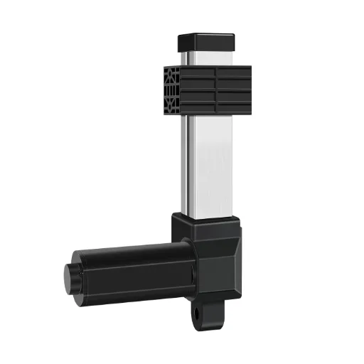
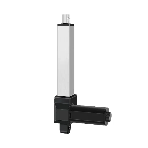
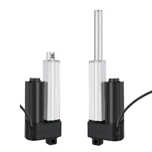
Hoodland engineers manufacture high quality electric linear actuators and complete control systems that are specifically designed to suit these very demanding environments. Instead of offering individual, fragmented parts, Hoodland concentrates on offering complete audited, technologically accurate motorized solutions with sophisticated, in-built intelligent overcurrent protection.
- Integrated Intelligent Overcurrent Protection: Hoodland’s proprietary control systems act as the vigilant brain for their linear actuators. Regardless of whether the micro-precision IP70/IP800 series or the heavy-duty IP6000 series (with the ability to provide an incredible 6000N of thrust) is used, the controllers continuously measure electrical current. In case an actuator is faced with a sudden physical impediment, which instantaneously results in a huge current spike in the motor, the overcurrent protection built into Hoodland will automatically stop the system. This active monitoring prevents motor incineration, protects structural integrity, and ensures user safety in medical and ergonomic applications.
- Strict Regulatory and Safety Compliance: Hoodland products are strictly produced under the ISO 9001 quality management systems. Their parts are fully certified to comply with CE (including Low Voltage Directive LVD and EMC) and RoHS, which will allow them to pass through the regulatory barriers in the European and international markets easily.
- Specialized EnvironmentalSafety: Hoodland has specialized product lines with an Ex ib IIA T6 Gb Explosion-proof certification to be used in highly volatile industries, such as petrochemicals or mining. This high-level safety standard demonstrates that the electrical and enclosure design is sound enough to avoid any internal arcing, thermal runaway or overcurrent incident to trigger an explosive gas environment.
- Engineering-First Customization: Hoodland is the leader in deep customization, as opposed to inflexible standard catalogs. Since they can incorporate the accurate position feedback (Hall Sensors/Potentiometers) that coordinate the various units, to the dialing of the exact stroke lengths and speeds, they make sure that the electromechanical integration is just perfect to the load and current limits that your specific needs and particular machine require. Every unit undergoes a rigorous 2-hour aging test before leaving the factory, guaranteeing a design life of over 30,000 cycles.
Ready to optimize your intelligent electromechanical design?Consult our engineering team to review your load requirements, system integration needs, and safety parameters for your next custom project.
Troubleshooting Common Overcurrent Device Failures and Tripping
Even the best-planned electrical systems will at some point in time have an overcurrent trip. For maintenance engineers and facilities managers, diagnosing the root cause of a tripped breaker or blown fuse quickly is vital to restoring operations and avoiding repeated failures.
- Differentiating Nuisance Tripping from True Faults
The most common complaint is a circuit breaker that “keeps tripping.” The first diagnostic step is to determine if the breaker is experiencing a nuisance trip or responding to a legitimate electrical hazard. Nuisance tripping often occurs when harmonic-rich loads (like variable frequency drives or massive banks of LED lighting) distort the electrical waveform, confusing the microprocessor inside advanced solid-state breakers. Additionally, if multiple heavy motors start simultaneously, their combined transient inrush current may exceed the breaker’s short-time delay setting, triggering a trip without an actual fault existing. In such instances, the problem can be solved by changing the Time-Current Curve (TCC) delay settings on an adjustable trip unit.
- Diagnosing Overload vs. Short Circuit Trips
If a thermal-magnetic breaker trips, you can often deduce the fault type by how the breaker behaves upon resetting.
- If you attempt to reset the breaker immediately and it refuses to latch (feeling springy or immediately snapping back), it likely tripped on overload. The internal bimetallic strip is still physically hot and bent. It will take you several minutes to have the metal cool down and resume its original shape before the latch will engage.
- When the breaker trips right away but in a violent way again, the millisecond the load is switched on (usually with a loud mechanical bang and a flash of light behind the panel), then you have a short circuit or ground fault. Do not repeatedly attempt to reset it. Repeatedly closing a breaker into a dead short degrades the internal contacts and risks an arc-flash explosion.
- Advanced Troubleshooting Techniques
When a dead short is suspected, use a high-voltage insulation resistance tester (Megger) to check the integrity of the wiring insulation between all phases and ground while the power is completely secured. Loose terminal connections are another insidious culprit. A loose lug increases localized resistance, generating massive I²R (current squared times resistance) heat that conducts directly into the breaker’s thermal element, causing it to trip on overload even when the measured circuit current is well below the rated maximum. Utilizing a thermal imaging camera (infrared thermography) on an operating panel under load is an excellent predictive maintenance strategy to spot these glowing, high-resistance connections before they cause a thermal trip or fire.

- The Danger of “Sizing Up”
The worst thing about troubleshooting is that it is assumed that a tripping breaker is “too small,” and a 20A breaker is replaced by a 30A breaker randomly to ensure that the equipment continues to operate. Breakers are specifically sized to protect the weakest link in the circuit—usually the wire gauge. The wire will now serve as the fuse by up-sizing the OCPD without enlarging the size of the conductor, which will gradually melt its insulation and lead to an unavoidable fire. Any changes to OCPD sizing must be accompanied by a full NEC load calculation and thermal analysis.