In the complex and high-stakes electrical engineering environment, protecting systems against abnormal electrical operation is not merely a best practice—it is a mandatory regulatory provision and the bedrock of reliable machine design. Whether you are designing an adjustable medical lifting bed, architecting a high-speed industrial automated assembly line, or engineering smart home furniture, understanding the precise mechanics of overcurrent is non-negotiable.
While traditional literature often focuses heavily on massive utility grids and high-voltage distribution switchgear, this comprehensive guide delves deep into overcurrent protection in electromechanical systems. We will deconstruct the basic differences between fault conditions, explore device sizing algorithms, and provide design engineers with the knowledge required to implement reliable linear actuator overload protection and safeguard internal DC motors against catastrophic failures.
What Is Overcurrent Protection and Why Is It Essential in Machine Design?
At its core, overcurrent protection is the engineered safeguard against any current that exceeds the rated capacity of equipment, the ampacity of a conductor, or the thermal limits of a motor winding.
To fully grasp why this is necessary, we must look at the underlying physics, specifically Joule’s First Law. The heating power produced by a conductor is proportional to the square of the current multiplied by the resistance:
P = I^2R
Because the current ($I$) factor is squared, even a marginal increase in current leads to an exponential surge in thermal energy. If left unchecked, this rapid thermal accumulation will degrade wire insulation, destroy the delicate copper windings inside DC motors, warp mechanical components, and ultimately ignite surrounding combustible materials.
The Role of Back-EMF in Motorized Systems
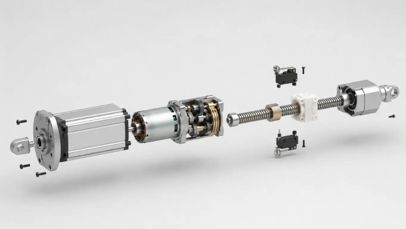
In linear motion systems, overcurrent is intimately tied to motor physics. When a DC motor spins, it generates a Back-Electromotive Force (Back-EMF) that naturally opposes the supply voltage, limiting the current drawn. However, when a motor is forced to slow down or completely stall due to a heavy mechanical load, this Back-EMF drops to zero. Consequently, the motor draws maximum current from the power supply—a phenomenon known as actuator locked rotor current.
For capital equipment and automated machinery, an overcurrent protection device (OCPD) is the absolute baseline for operational reliability. It ensures that when a mechanical failure occurs, it does not cascade into a catastrophic electrical fire.
The Physics of Linear Motion Failures: 3 Main Overcurrent Types
A widespread myth among beginner electrical designers is the interchangeable use of the terms “overload” and “short circuit.” In engineering, they represent entirely different physical phenomena requiring distinctly different protection strategies, especially when dealing with motors and linear actuators.
Overload (The Progressive Thermal Threat)
An overload occurs when equipment operates with a current greater than its normal full-load rating, yet the current remains confined within the intended conductive path. This is a gradual, progressive thermal process.
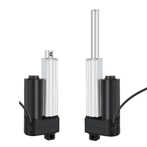
In linear motion design, this is the most frequent cause of system failure. Consider an industrial electric push rod rated for 6000N of thrust. If an operator programs it to lift an 8000N load, or if the moving mechanism suffers from severe structural binding (due to rust, misalignment, or an obstacle), the motor will fight to maintain torque. As its RPM drops, the current skyrockets.
Knowing how to protect actuators from mechanical jamming relies entirely on implementing accurate, time-delayed overload protection. The protection must allow for brief, harmless startup surges (inrush current) but cut power before the sustained overload incinerates the motor windings.
Short Circuit (The Instantaneous Explosive Threat)
A short circuit is a violent, instantaneous event where an unintended, near-zero resistance path is established between two conductors of different potentials (e.g., Line-to-Line, or positive-to-negative in a DC system).
According to Ohm’s Law ($I = V/R$), when resistance ($R$) drops to near zero, the current ($I$) spikes to astronomical levels, often reaching thousands of amperes in a fraction of a millisecond. This energy bypasses the intended mechanical load entirely, leading to instant arcing, metal vaporization, and potential arc-flash explosions. Protection against this condition relies on extremely fast-acting magnetic or solid-state mechanisms to clear the fault before the peak let-through energy destroys the control cabinet.
Ground Fault (The Hidden Safety Threat)
A ground fault is a specific type of short circuit where the unintended conductive path connects an energized phase to the earth or the metal chassis of a machine. Ground faults are particularly insidious because they can involve very low currents if the ground path has high impedance.
While a 2-ampere fault might not trip a standard 20A industrial breaker, it is more than enough to cause lethal electrocution to a human operator touching the energized metal frame of a hospital bed or an industrial gantry. Ground fault protection (like GFCI or RCD devices) specifically monitors the imbalance between outgoing and returning currents, ensuring absolute operator safety.
| Fault Type | Current Multiple | Trigger Condition in Actuators | Time to Trip | Potential Hazard |
| Overload | 1.3x to 6x of rated current | Mechanical jamming, exceeding rated load capacity (e.g., lifting >6000N). | Seconds to Minutes (Inverse-time delay) | Thermal degradation of motor windings, eventual motor burnout. |
| Short Circuit | 10x to 1000x+ of rated current | Insulation failure, physical bridging of phase conductors in control panel. | Milliseconds (≤ 10ms – 20ms) | Arc flash, explosive destruction of control cabinet. |
| Ground Fault | Varies (mA to kA) | Moisture ingress, compromised grounding path connecting energized phase to metal chassis. | Milliseconds to Seconds | Lethal electrical shock to operators touching the equipment frame. |
AC vs. DC Overcurrent Protection: The Electromechanical Challenge
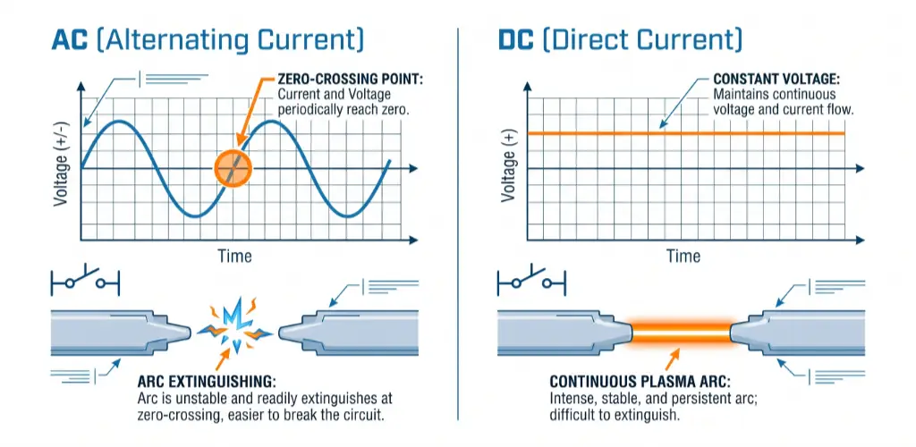
As the industry shifts toward battery-powered automation and low-voltage control systems, engineers must understand the critical difference between Alternating Current (AC) and Direct Current (DC) protection. Most linear actuators utilize DC motors (12V, 24V, or 48V), which presents a unique engineering challenge.
- AC Arc Extinction: In an AC circuit, the voltage naturally drops to zero (zero-crossing) 100 or 120 times per second, depending on the grid frequency. When an AC breaker opens during a fault, the resulting electrical arc is easily extinguished as the voltage hits this zero point.
- The DCArc Hazard: DC power is a continuous, unyielding flow. When contacts open to interrupt a severe DC fault, the current attempts to keep flowing, drawing a massive, continuous plasma arc across the air gap.
Therefore, overcurrent protection for DC motors requires specialized components featuring magnetic blowouts or complex arc chutes designed to forcibly stretch, cool, and snap the DC arc. Never use an AC-rated breaker in a DC motor circuit—it will likely weld its contacts shut during a fault, offering zero protection.
Main Types of Overcurrent Protection Devices (OCPDs) for Machinery
Selecting the correct OCPD requires balancing three critical parameters: Response Time (how fast it clears the fault), Interrupting Rating (the maximum short-circuit current it can safely stop), and Resettability.
Traditional Fuses and Circuit Breakers
- Fuses: The oldest, yet highly reliable form of protection. Inside the fuse body lies a precise metallic element (often a silver alloy) surrounded by silica sand. Under extreme Joule heating, the element melts, breaking the circuit. While they offer incredible interrupting ratings (often capable of stopping 100kA+ short circuits), they are sacrificial. A blown fuse means machine downtime until a physical replacement is installed.
- Thermal-Magnetic Circuit Breakers: These resettable mechanical switches use a dual-trip mechanism. A bimetallic strip bends under gradual heat to protect against overloads, while a magnetic solenoid instantly pulls the breaker open during a massive short circuit. They are standard in industrial panels due to their easy reset capabilities.
Solid-State Solutions (eFuses and PTCs)
For compact PCB-level motor control, mechanical devices are often too bulky or slow.
- PTCs (Polymeric Positive Temperature Coefficient): Commonly known as resettable fuses, PTCs consist of a conductive polymer matrix. During an overcurrent event, the polymer heats up, expands, and breaks the conductive paths, causing resistance to spike exponentially. Once power is removed and it cools, it resets to a low-resistance state.
- eFuses (Electronic Fuses): These silicon-based integrated circuits utilize an internal power MOSFET to actively monitor and restrict current flow. They offer microsecond ($\mu s$) response times, making them essential for protecting sensitive motor driver ICs and microprocessors from transient voltage and current spikes.
Advanced Sizing Strategies: Beyond the 125% Rule
Specifying protection for an electromechanical system is a rigorous analytical procedure. Simply matching the wire’s ampacity is a risky oversight that leads to system instability.
The Baseline Calculation
Electrical codes universally mandate that an OCPD must be sized to handle 100% of the non-continuous load plus 125% of the continuous load (any load operating for 3 hours or more).
For example, if your multi-actuator setup draws a continuous 10 Amps, the breaker must be sized at a minimum of 12.5A to prevent the breaker’s internal thermal elements from degrading under constant heat.
Decoding Time-Current Curves (TCC) for Motors
To properly size overcurrent protection for DC motors, engineers must master the Time-Current Curve (TCC). A TCC is a logarithmic graph where the X-axis represents current magnitude and the Y-axis represents the time taken to trip.
Motors require a massive surge of current to overcome initial mechanical inertia. This startup surge can be 3 to 6 times the normal Full Load Amps (FLA). If you specify a “fast-acting” breaker, the motor’s normal startup surge will intersect the breaker’s trip zone, causing a frustrating “nuisance trip” every time the actuator moves. Engineers must select a “Motor Circuit Protector” with a delayed thermal characteristic—a curve that safely rides the initial 3-second startup surge but aggressively trips if a true locked-rotor condition persists.
Global Standards and Compliance: UL, IEC, and NEC
A poorly certified OCPD is a massive liability. It will fail municipal inspections and void insurance policies. When engineering products for a global market, adherence to stringent standards is required:
- NEC Article 240 (North America): The National Electrical Code strictly governs how and where overcurrent protection must be applied to protect conductors and equipment.
- UL 489 vs. UL 1077: Underwriters Laboratories defines strict testing limits. UL 489 breakers are robust enough for main branch protection. UL 1077 devices are merely “Supplementary Protectors” and must be backed up by a primary fuse or UL 489 breaker. Misapplying a UL 1077 device in a motor control circuit is a dangerous code violation.
- IEC 60947-2 (Global/Europe): This standard dictates the operational performance of industrial low-voltage circuit breakers under extreme short-circuit conditions, crucial for CE-marked automation equipment.
Diagnosing and Troubleshooting Motion Control Faults
Even meticulously designed systems occasionally experience a trip. For maintenance engineers, rapidly diagnosing the root cause is vital.
Differentiating Nuisance Tripping from True Faults
If a breaker trips constantly, the first step is determining if it’s a nuisance trip or a real hazard. In multi-actuator systems, if several heavy motors start simultaneously without programmed delays, their combined transient inrush current will exceed the breaker’s short-time threshold. This is solved via software sequencing, not by blindly upsizing the breaker.
Overload vs. Short Circuit Signatures
- Overload Signature: If you attempt to reset a tripped thermal-magnetic breaker immediately and it refuses to latch (feeling “springy”), it tripped on overload. The internal bimetallic strip is still physically hot. You must wait several minutes for it to cool and reshape.
- Short Circuit Signature: If the breaker violently trips the exact millisecond the load is switched on—often accompanied by a loud mechanical bang or a flash—you have a dead short. Do not repeatedly attempt to reset it, as closing a breaker into a dead short severely degrades its internal contacts.
The Danger of “Sizing Up”: The most dangerous troubleshooting mistake is replacing a tripping 20A breaker with a 30A breaker. Breakers are sized to protect the weakest link (the wire). Upsizing the OCPD forces the wire to act as the fuse, guaranteeing an eventual electrical fire.
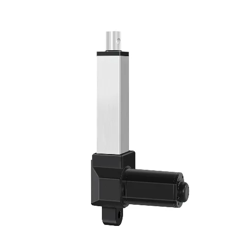
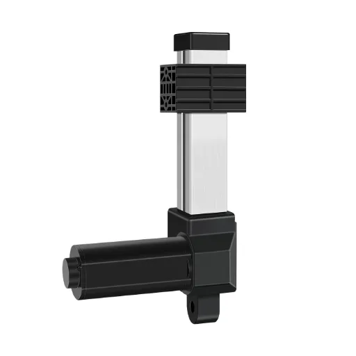
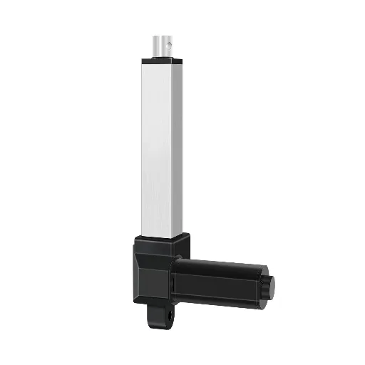
Sourcing Reliable Motion Protection: The Hoodland Advantage
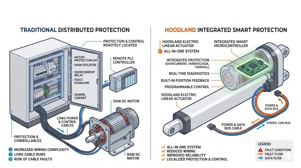
When designing complex industrial power matrices, highly automated medical equipment, or high-end adjustable smart furniture, relying on generic external protection devices introduces severe compliance risks. Precise current coordination and intelligent fault clearing are non-negotiable to prevent motor burnout and mechanical damage.
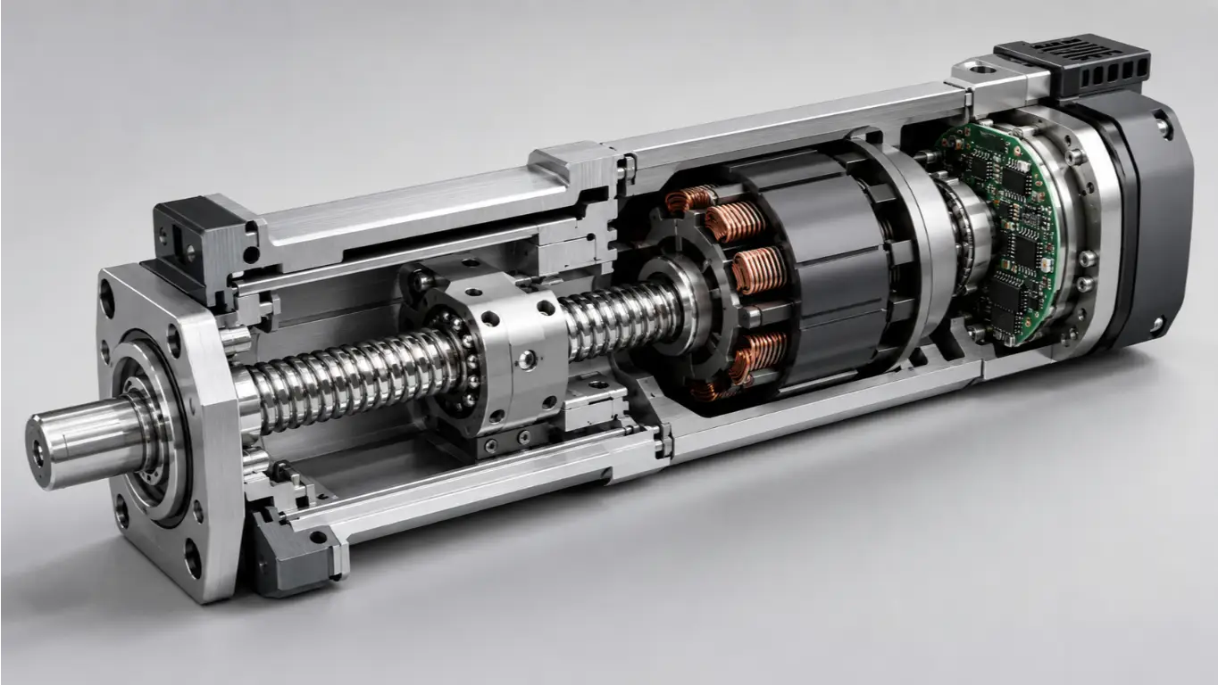
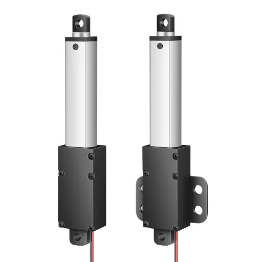
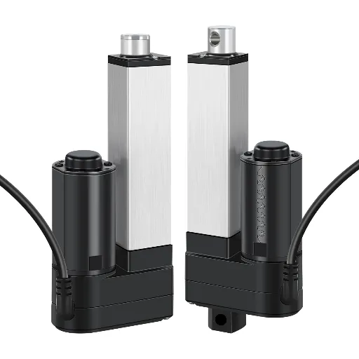
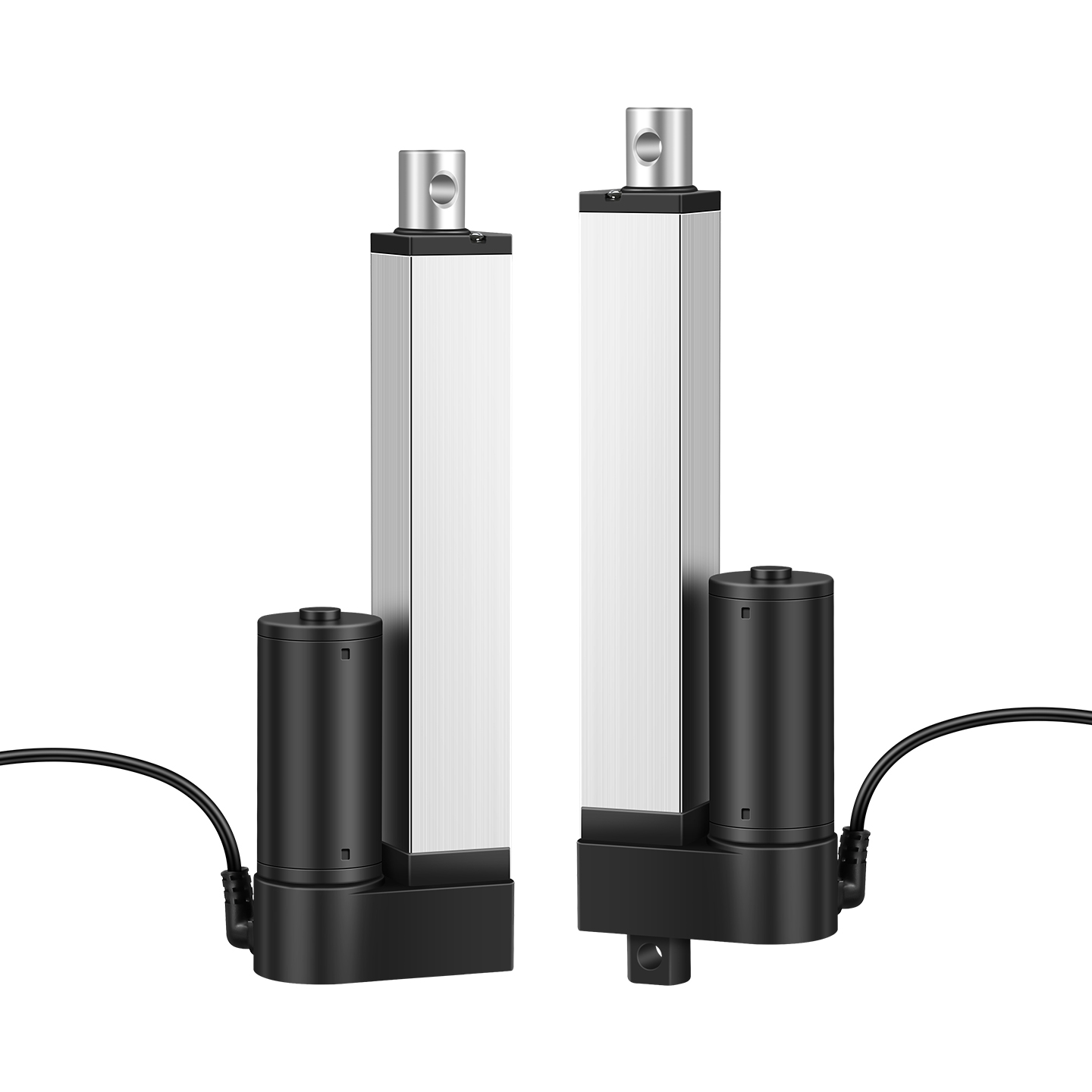
At Hoodland, we engineer and manufacture complete, technologically accurate Electric Linear Actuators equipped with sophisticated, in-built intelligent overcurrent protection. By integrating our solutions, you shift the engineering burden of current coordination directly to our experts.
Integrated Smart Controller Monitoring
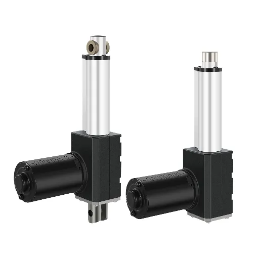
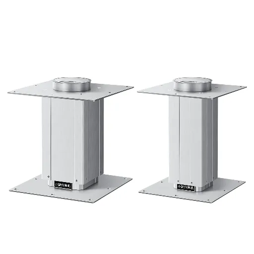
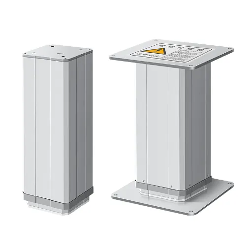
The absolute best way to implement linear actuator overload protection is directly at the source. Hoodland’s proprietary control systems act as the vigilant brain for our actuators. Whether you are deploying the micro-precision IP70 series or the heavy-duty IP6000 series (capable of a massive 6000N of thrust), our internal controllers continuously sample electrical current at the microsecond level.
Active Mechanical Jamming Prevention
If a Hoodland actuator faces a sudden physical impediment—triggering a severe actuator locked rotor current—our internal smart overcurrent protection automatically halts the motor instantaneously. This active, software-driven monitoring prevents motor incineration, protects your mechanical linkages from bending, and ensures absolute user safety in ergonomic and medical applications.
Strict Regulatory & Environmental Safety

Hoodland products are manufactured under rigorous ISO 9001 quality management systems and are fully certified to CE (including LVD and EMC) and RoHS standards. Furthermore, for highly volatile industries such as petrochemicals or mining, Hoodland offers specialized product lines carrying Ex ib IIA T6 Gb Explosion-proof certification. This proves our electromechanical enclosures and current-limiting designs are robust enough to prevent any internal arcing or thermal runaway from igniting an explosive gas environment.
Engineering-First Customization
Unlike inflexible standard catalogs, Hoodland excels in deep customization. Because we manage the entire manufacturing process—from internal screw winding to the electronic controller—we precisely dial in the overcurrent thresholds to match your specific stroke lengths, speeds, and structural load limits. Every single unit undergoes a stringent 2-hour aging test before leaving the factory, guaranteeing a stabilized 30,000+ cycle design life.
Ready to optimize your intelligent electromechanical design?
Stop wrestling with complex breaker sizing charts, nuisance tripping, and burned-out motors. Rely on a system that protects itself.
Consult the Hoodland engineering team today to review your load requirements, system integration needs, and safety parameters for your next custom project. With our philosophy of “Fast, Not Rushed,” we ensure your linear motion system is defined right the first time.