Solenoid vs Linear Actuator: The Ultimate 2026 Engineering Guide
Resolving the Industry Ambiguity: Linear Motion versus Valve Control
Specifying the wrong linear motion component doesn’t just blow your procurement budget; it compromises your entire mechanical assembly. A mismatched drive system leads to erratic positioning, catastrophic thermal failures, and skyrocketing maintenance costs. When engineers evaluate solenoid vs linear actuator technologies, the decision extends far beyond a simple price comparison. It requires a deep understanding of energy conversion physics, duty cycle limitations, and long-term Total Cost of Ownership (TCO).
Before we dissect stroke lengths and force curves, we must address a prevalent terminology trap that pollutes search engine results and engineering forums alike: the critical difference between valve actuation and motion actuation.
When sourcing components, many buyers inadvertently mix up devices designed to control fluid dynamics with those engineered to produce physical, mechanical displacement. Valve Actuators are essentially the knobs on your industrial pipeline. Whether they are pneumatic, electric, or solenoid-driven, their sole purpose is to open or close a valve to regulate the flow of water, gas, or oil. Conversely, Linear Actuators and Linear Solenoids are engineered to push, pull, lift, or position physical objects. Think of them as a robotic arm pushing open a heavy drawer, adjusting a medical bed, or locking a mechanical vault.
This guide strictly evaluates the latter: electromechanical technologies that convert electrical energy into direct linear motion. If you are designing physical machine kinematics, you are in the right place.
First Principles of Energy Conversion
To understand why a solenoid and an electric actuator exhibit such vastly different performance boundaries, we must look at the root mechanics of how they translate power into motion. It is a battle between direct electromagnetic fields and mechanical gearing.
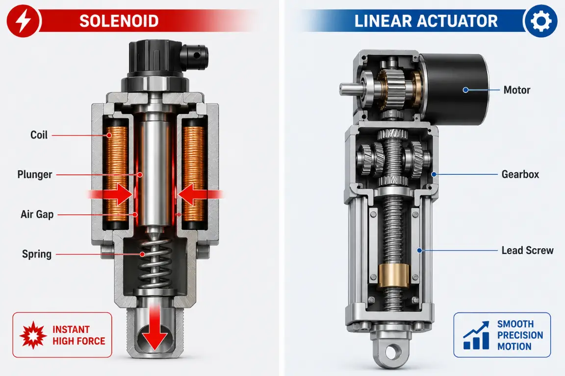
The Solenoid: Direct Electromagnetic Drive
A linear solenoid represents the purest form of direct energy translation. Its construction is relatively simple: a coil of copper wire housing a movable ferromagnetic core (the plunger) and a return spring. When an electrical current passes through the coil, it instantly generates a magnetic field. This field overcomes the mechanical return spring, violently sucking the plunger into the center of the coil.
Think of it as a “magnetic bullet”—it either fires or retracts. There is no intermediate gearing, no friction from a transmission, and almost zero moving parts. However, this mechanism is bound by the Air Gap Effect. According to the laws of electromagnetism, the magnetic force is inversely proportional to the square of the distance (the air gap) between the plunger and the magnetic stop. The further the plunger is from the coil’s center, the exponentially weaker the pull becomes. This single law of physics dictates the fundamental limitation of all solenoids.
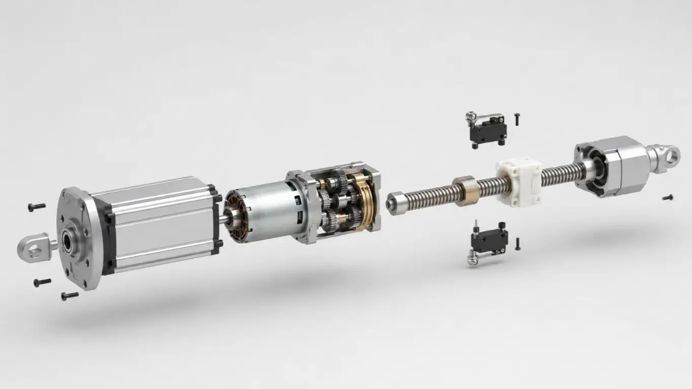
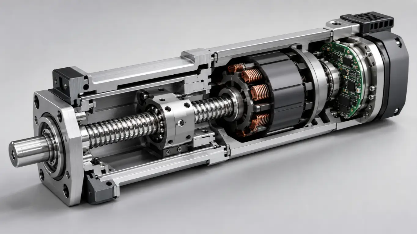
The Linear Actuator: Electromechanical Gear Conversion
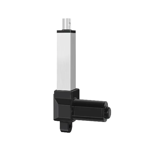
Unlike the direct-drive solenoid, an electromechanical linear actuator uses a cascaded, physical energy conversion process. An electric motor (DC, AC, or Stepper) generates rotational torque. This rotation is fed into a reduction gearbox, which magnifies the torque at the expense of speed. The gearbox then turns a lead screw (such as a standard Acme thread or a high-efficiency Ball screw), which drives a threaded nut forward or backward along the shaft.
Imagine a mechanical car jack powered by a sophisticated transmission. It moves significantly slower than a magnetic bullet, but thanks to mechanical advantage, it can effortlessly generate and sustain a massive, constant force over an almost infinite distance.
The Core Performance Matrix
When the CAD blueprint is on the table, vague descriptions fail. Let’s look at the hard, quantitative numbers dictating your selection.
The Force and Stroke Limit Curve
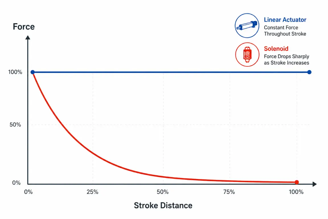
The most defining contrast between these two components is how their push/pull force behaves over a distance (stroke).
| Dimension | Linear Solenoid | Linear Actuator | Engineering Verdict |
|---|---|---|---|
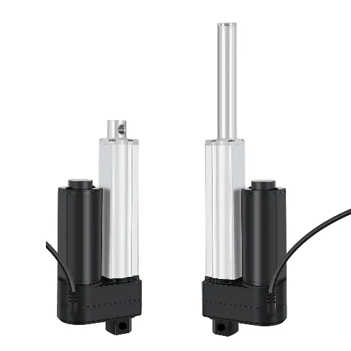
| Max Stroke (Travel) | Typically < 2 inches (50mm) | Up to 39+ inches (1000mm+) | Redline: If stroke > 2″, avoid solenoids to prevent severe force drop-off. |
| Force Curve | Exponential decay (weak start, strong end) | Constant thrust across entire stroke | Actuators are mandatory for pushing heavy loads uniformly. |
| Load Capacity | Grams to ~50 lbs | Up to 2,000+ lbs (approx. 9000N) | Actuators dominate heavy-duty industrial applications. |
If you try to use a solenoid to push a 10-pound load over a 3-inch distance, the magnetic field at the starting position will be too weak to overcome static friction. An actuator, however, applies its maximum rated torque from the very first millimeter of travel.
Speed and Response Time Differentials
A solenoid operates with explosive immediacy. Because there are no gears to spool up, solenoids typically boast response times of < 30 milliseconds. They are the undisputed champions for high-speed sorting mechanisms and rapid-fire punch presses. Conversely, a linear actuator operates at a smooth, continuous velocity—typically ranging from 0.2 to 2.0 inches per second. Due to motor inertia and gear engagement, there is a slight mechanical delay upon startup. You use an actuator when you need controlled, steady displacement.
The Duty Cycle Trap and Thermal Management
Many procurement teams fall victim to the “cheap solenoid trap,” focusing only on the unit price while ignoring the devastating consequences of heat dissipation under continuous load. In the engineering world, Duty Cycle is the percentage of time a device is active compared to its resting time:
Duty Cycle = [ON Time / (ON Time + OFF Time)] × 100%
Here lies the critical hidden failure point: Holding Force. If your mechanism needs to push a load and hold it there for 5 minutes, a standard linear solenoid requires continuous electrical power (100% duty cycle) to maintain that magnetic field. This constant current causes extreme thermal rise. Within minutes, the coil temperature can exceed NEMA insulation limits, melting the internal wires and causing a catastrophic short circuit. It is akin to holding a 50kg bag of cement in your arms all day—eventually, your muscles will collapse.
Linear actuators inherently solve this through Self-locking mechanics. The physical friction of their lead screws (especially Acme threads) prevents back-driving. Once the actuator reaches the desired position, you cut the power. It consumes zero energy and generates zero heat while sustaining tons of static holding force. It is the equivalent of placing that 50kg bag of cement on a solid steel table.
Control Logic: Binary Operation versus Proportional Positioning
Control architecture is another non-negotiable variable. A solenoid is strictly binary: logic state 1 or 0, fully extended or fully retracted. You cannot tell a solenoid to stop at the 45% mark. For modern industrial designs requiring multi-point positioning—such as adjusting the backrest of a medical bed, synchronizing a standing desk, or tilting solar trackers—an electromechanical actuator utilizing closed-loop feedback (via built-in encoders or potentiometers) is mandatory.
The Precision vs. Space Dilemma: A Modern Solution
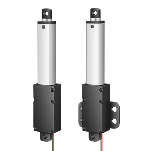
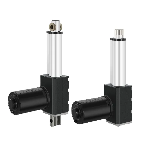
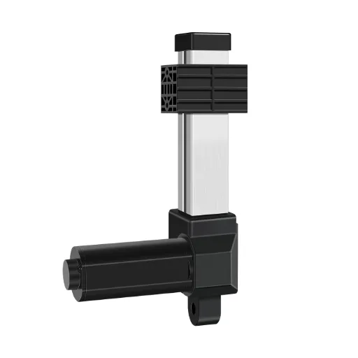
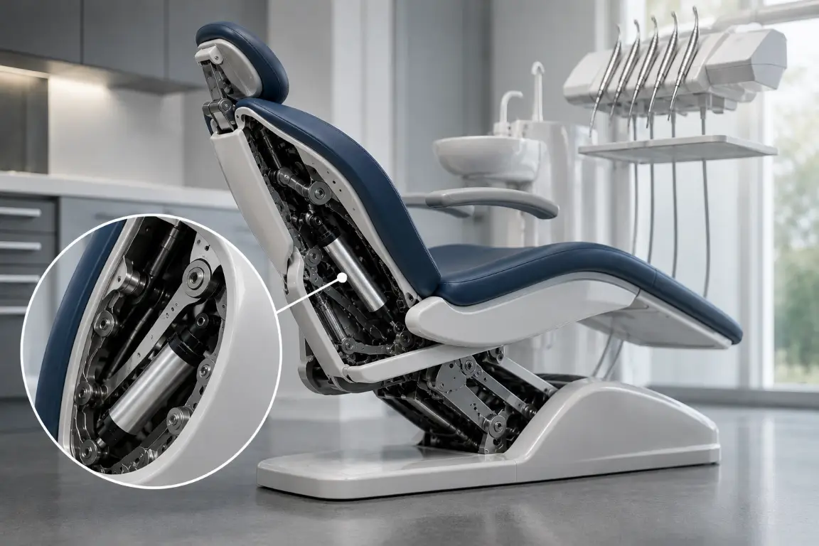
Historically, mechanical engineers faced a brutal compromise: they needed the precise, multi-point stopping capability of a linear actuator, but their product (like a hidden smart cabinet or a highly compact dental chair) had practically zero installation space. Forced into a corner, they would settle for a noisy, binary solenoid and attempt to build complex external latches to compensate.
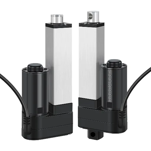
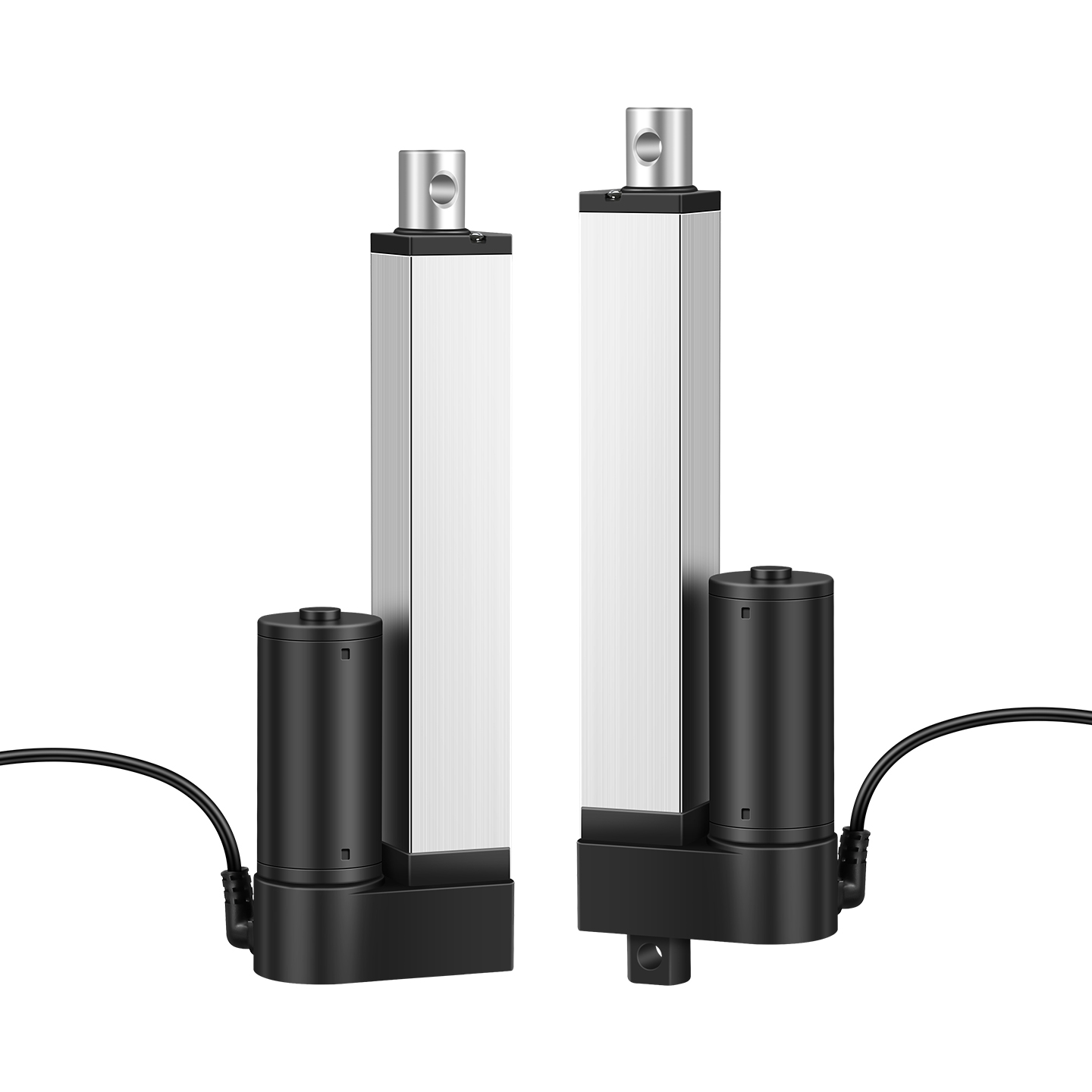
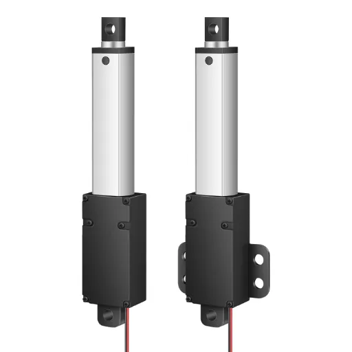
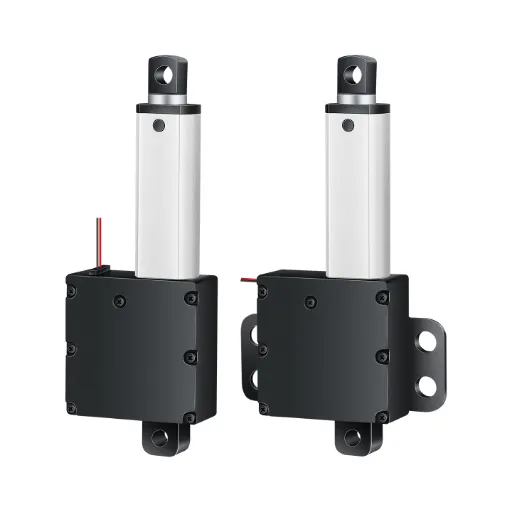
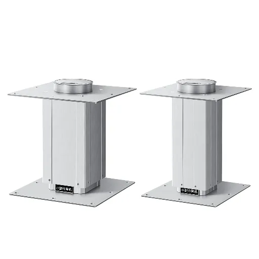
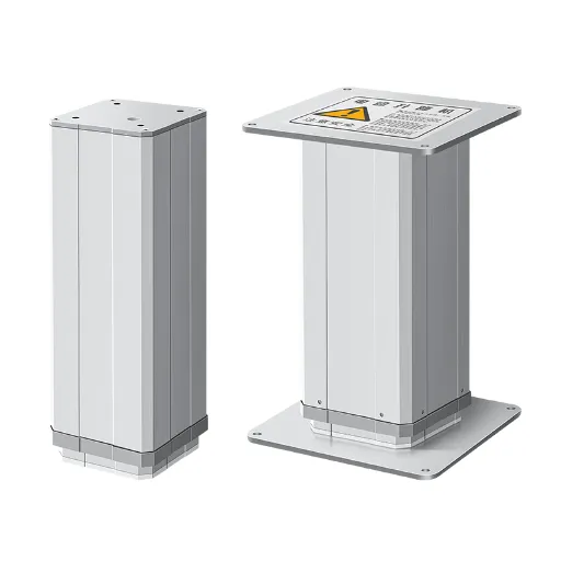
The industry has since evolved to eliminate this compromise. Hoodland’s IP70 and IP800 Micro-Precision Series are engineered specifically for highly restricted enclosures. These compact units do not just solve the space constraint; they integrate built-in Hall Sensors, allowing your PLC or control board to execute flawless memory positioning and multi-leg synchronization.
More critically, leveraging deep-rooted precision molding expertise, Hoodland engineered these micro-units to operate at a <50dB whisper-quiet level. This is the exact reason top-tier medical device and smart furniture manufacturers deploy them—to eliminate the “tractor-like” mechanical grinding noise of standard actuators, ensuring a premium, anxiety-free user experience without sacrificing spatial efficiency.
Environmental Resilience and IP Ratings
The survival of your motion control component depends heavily on its operating environment. Picture an automated baking facility filled with airborne flour dust. If you use a standard open-frame solenoid, the airborne particulates will inevitably settle on the plunger guide. The added friction alters the delicate magnetic balance, leading to incomplete strokes and eventual jamming. While tubular solenoids offer slightly better protection, securing a true high-level seal around a fast-moving, unlubricated core is structurally difficult.
Linear actuators, however, are fully enclosed systems housed in extruded aluminum or stainless steel. They effortlessly achieve IP68 or IP69K ratings, meaning they can withstand high-pressure, high-temperature chemical washdowns in food processing plants. Furthermore, specialized actuator models carry strict Ex ib IIA T6 Gb explosion-proof certifications, making them the only legal and safe choice for operating heavy mechanisms in petrochemical refineries or mining operations where a single spark could be disastrous.
Total Cost of Ownership: A 5-Year Financial Breakdown
B2B procurement psychology often fixates on the initial unit price. A solenoid might cost $15 to $30, while an industrial-grade actuator sits at $150 to $300. But what happens in year three of a heavy-duty, 24/7 manufacturing cycle? When a mismatched solenoid burns out due to duty-cycle abuse, the cost is not just the $15 replacement part. The resulting machine downtime in a modern manufacturing plant can cost upwards of $5,000 per hour, dwarfing the initial “savings.”
Securing Long-Term ROI Through Manufacturing Standards
A component’s theoretical lifespan only translates to actual financial savings if it is backed by rigorous quality control. Buying cheap, off-the-shelf actuators introduces high replacement frequencies and immense hidden labor costs when engineers are forced to fabricate custom brackets just to make the parts fit.
To lock in long-term ROI, elite engineering teams partner with source factories that guarantee baseline reliability. For instance, Hoodland enforces a stringent 30,000-cycle design life across its industrial lines, subjecting every single unit to a mandatory 2-hour aging test under load before shipping. This ISO9001, CE, and RoHS certified process virtually eliminates “out-of-the-box” failures.
Beyond durability, utilizing a manufacturer with robust in-house molding and CNC machining capabilities pays immediate dividends during assembly. Instead of wasting expensive engineering hours modifying standard parts, Hoodland delivers “plug-and-play” systems—tailoring specific stroke lengths, precision-cutting mounting bases, and supplying proprietary controllers that integrate seamlessly into your existing architecture.
The 10-Second Engineering Decision Tree
Stop guessing and avoid the endless debate. Apply this strict cascading logic to determine the exact motion component for your mechanical assembly. For over 90% of complex industrial and commercial designs, the choice points definitively in one direction.
* Note: Solenoids cannot perform multi-point positioning.
* Note: This requires zero-energy self-locking threads.
* Warning: Requires strict thermal monitoring to prevent coil burnout.