How Long Do They Last? Calculating Electric Linear Actuator Lifespan
When engineering a new piece of automated machinery, relying on a static “estimated lifespan” from a basic product brochure is a recipe for catastrophic downtime. In industrial automation, medical equipment, and precision manufacturing, the lifespan of an electric linear actuator is not a fixed expiration date stamped on a box; it is a highly variable engineering outcome dictated by the laws of physics, specific duty cycles, and environmental realities.
Consider a stark contrast: The exact same actuator model used in a solar tracking system—adjusting its angle just twice a day—might operate flawlessly for over a decade. However, place that identical unit in a high-speed packaging line cycling 30 times a minute, and it may suffer fatigue failure within three months.
To accurately predict and extend longevity, we must move away from guesswork. This guide will dissect the mechanical, electrical, and environmental variables that determine actuator survival, and provide you with the exact formulas needed to calculate life expectancy.
The Reality of Electric Linear Actuator Lifespan: Beyond the Spec Sheet
Many procurement managers ask, “Will this actuator last 5 years?” The engineering answer is always: “It depends on the work you are asking it to do.”
An electric linear actuator’s lifespan is a function of multiple interacting variables: Lifespan = f(Load, Duty Cycle, Environment, Component Fatigue).
Just as a set of car tires will wear out completely differently depending on whether they are driven on smooth highways or jagged gravel roads, an actuator’s internal components degrade at different rates depending on the application. To understand how long an actuator will last, we must first understand how it dies.
The Actuator Bucket Effect: Which Component Fails First
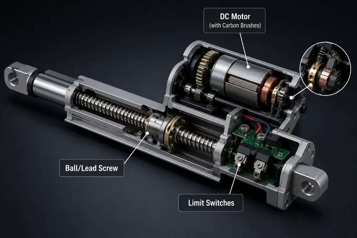
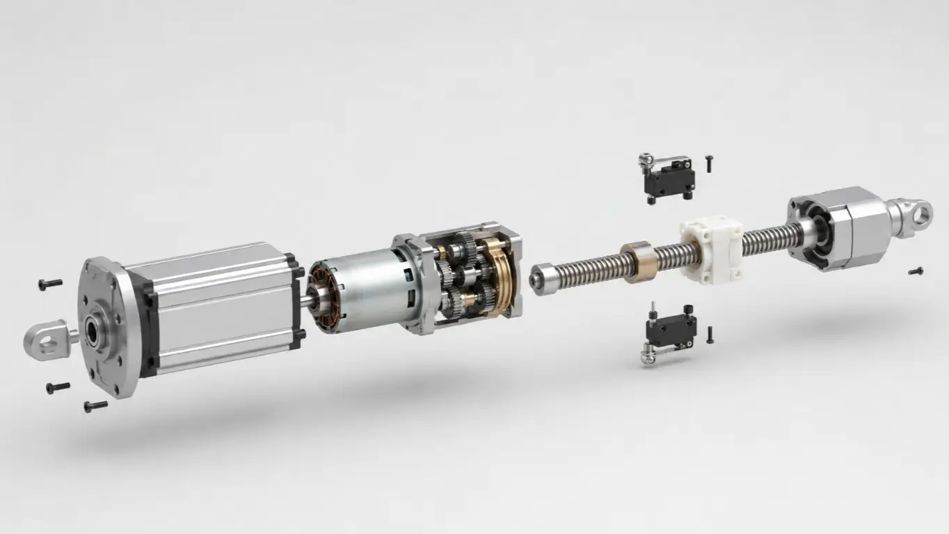
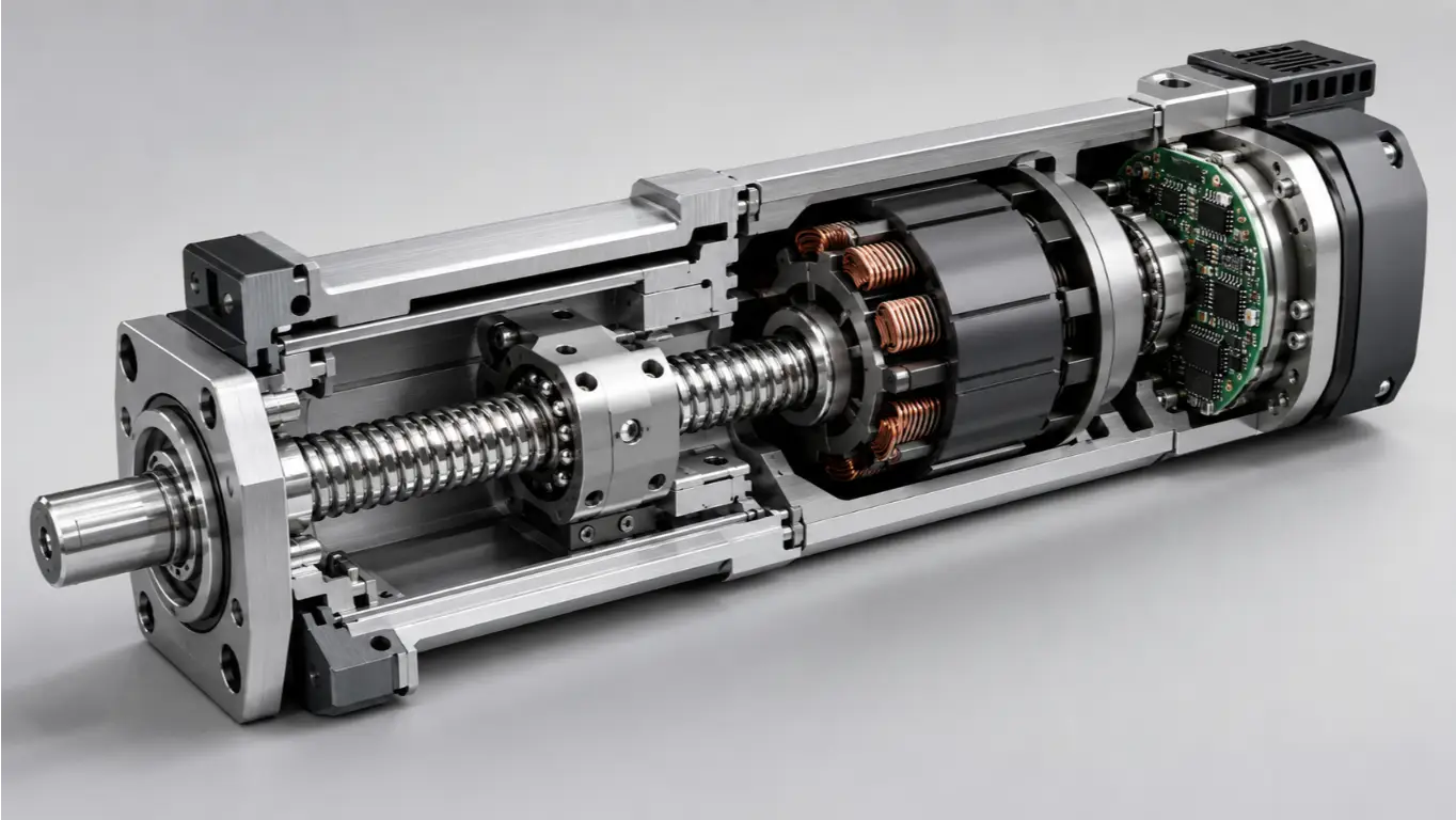
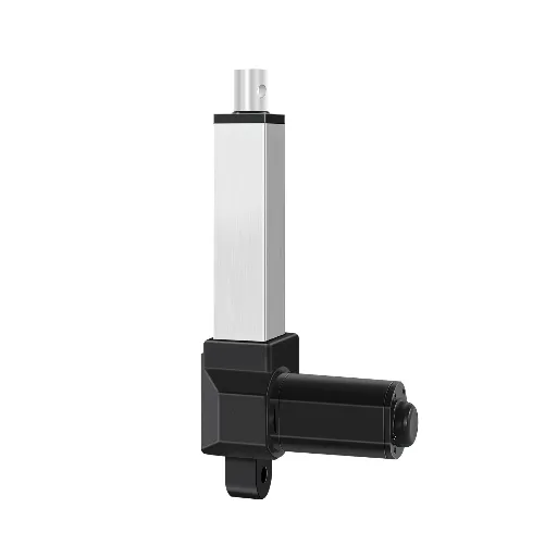
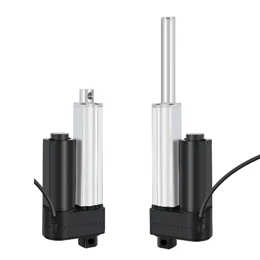
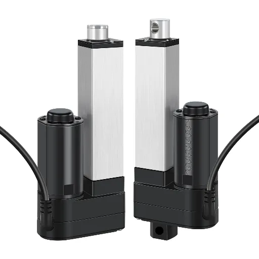
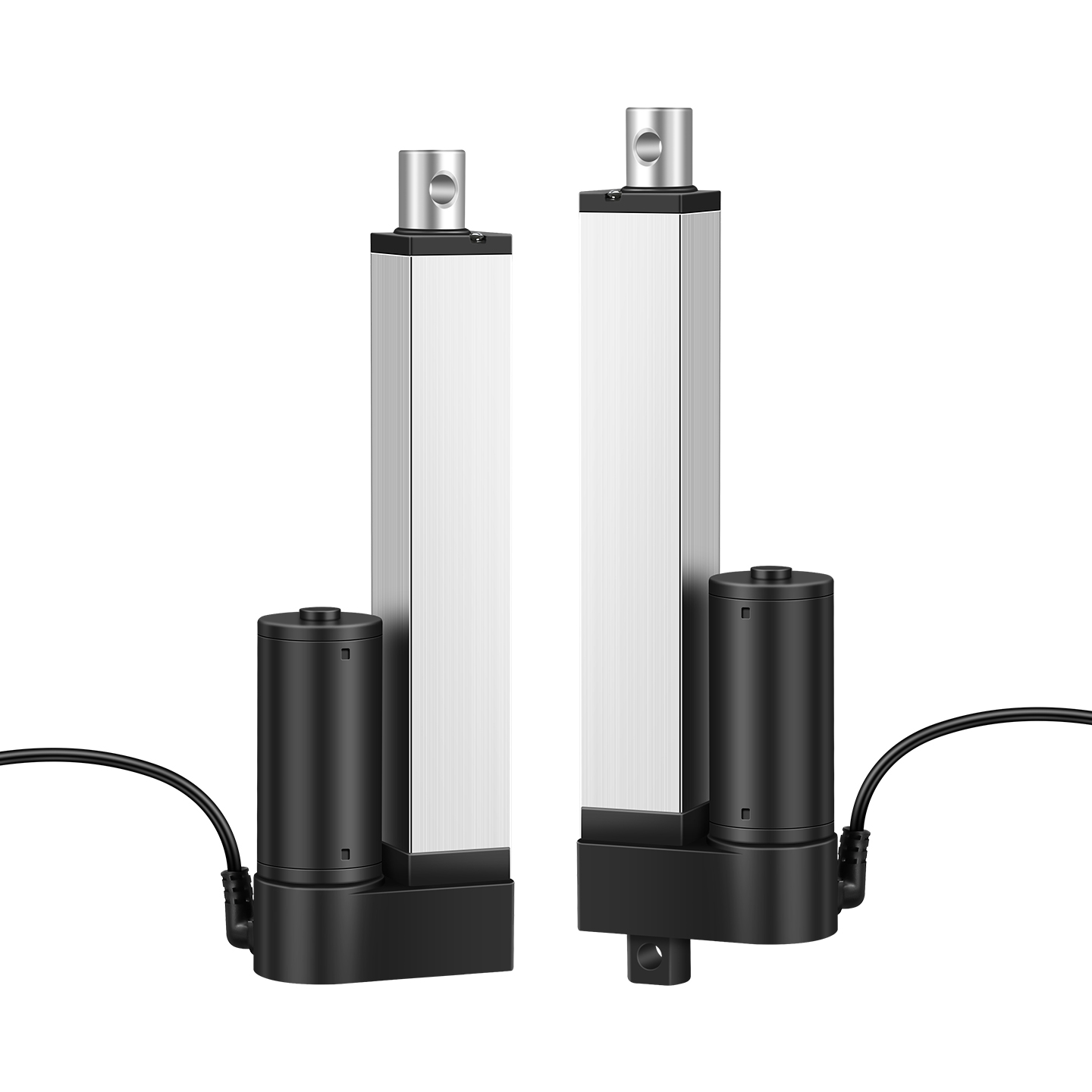
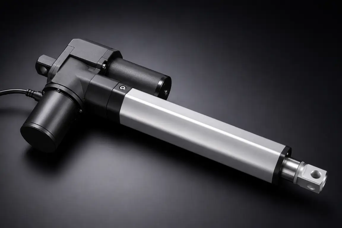
An actuator is not a solid block of metal. It is a complex electromechanical system comprising a motor, gears, a lead/ball screw, bearings, and electrical limit switches. According to the “bucket effect” (or the theory of constraints), the entire system will only last as long as its shortest-lived component.
Mechanical Fatigue: Screw and Nut Wear
The primary mechanical failure point in heavy-duty applications is the drive mechanism. As the screw and nut repeatedly process dynamic loads, they experience microscopic surface degradation. In high-performance ball screws, this eventually manifests as brinelling—a severe fatigue spalling where the intense, localized pressure of the steel balls causes microscopic flakes of the hardened steel track to break away.
Think of it like a heavily loaded truck repeatedly driving over the same stretch of asphalt; eventually, potholes form. Over time, this wear increases the backlash (play) in the shaft, destroying the positioning precision of the actuator and eventually leading to a mechanical jam.
Electrical Exhaustion: DC Motor Brushes and Limit Switches
It is a common blind spot for mechanical engineers to focus solely on the screw, only to have the actuator fail due to electrical exhaustion.
In applications requiring short strokes and high frequencies, the extreme starting and stopping current spikes will physically burn out the DC motor’s carbon brushes long before the steel screw shows signs of wear. Similarly, internal micro-switches can suffer contact welding after hundreds of thousands of electrical arcing events.
Engineering Insight & Quality Control: To prevent this premature electrical mortality, top-tier industrial manufacturers like Hoodland enforce a mandatory 100% quality inspection alongside a strict 2-hour dynamic aging test (Aging Test) on every unit prior to shipping. This front-loaded stress testing is the industry gold standard, ensuring that the electrical components, thermal management, and motor brushes can survive the rigorous demands of medical or heavy industrial environments without “infant mortality” failures.
Dynamic Load vs Static Load: The Fatigue Catalysts
One of the most fatal sizing errors an engineer can make is confusing static load with dynamic load.
- Static Load is the maximum weight the actuator can hold safely when powered off and stationary. It is a measure of structural integrity and self-locking capability—much like a weightlifter holding a barbell locked in place over their head.
- Dynamic Load is the weight the actuator can physically push or pull while in motion. It tests the material’s fatigue limit.
Exceeding the dynamic load rating does not just shave a few days off the lifespan; it triggers a catastrophic collapse of the wear curve. In mechanical engineering, there is an absolute rule regarding ball screw systems: life is inversely proportional to the cube of the load.
This means if you double the operating load on an actuator, its mechanical lifespan does not reduce by half—it plummets to one-eighth of its original expectancy. Always size your actuator so that your working load is comfortably below the maximum dynamic load rating.
Duty Cycle and Heat: The Silent Killers of Actuator Motors
Heat is the ultimate enemy of electrical insulation, motor windings, and internal lubrication. An actuator’s duty cycle dictates how much heat it will generate and how much time it has to dissipate that heat into the surrounding air.
Duty cycle is calculated using a straightforward ratio:
Duty Cycle % = [On Time / (On Time + Off Time)] × 100
If an actuator is rated for a 25% duty cycle, and it takes 2 minutes to complete a full loaded stroke, it absolutely must remain off for 6 minutes to cool down. Forcing a 25% duty cycle actuator to run at 50% will inevitably cause thermal overload. The copper coil insulation will melt, creating an internal short circuit, permanently destroying the unit from the inside out. Respecting the duty cycle is non-negotiable for motor longevity.
The Lead Screw vs Ball Screw Lifespan Dilemma
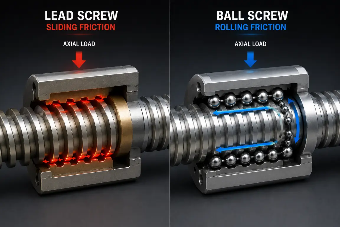
When selecting the internal drive mechanism, engineers must choose between sliding friction and rolling friction. This choice drastically alters both the efficiency and the wear curve of the device.
Acme/Lead Screws: Friction and Heat Limitations
Lead screws (or Acme screws) utilize sliding friction between the metal screw threads and the nut (often made of bronze or a self-lubricating polymer like POM). This results in an efficiency rating of only 30% to 40%. The remaining 60% of the energy is converted directly into friction heat. Consequently, lead screws are strictly limited to low duty cycles. Pushing them too hard will cause the nut to overheat, deform, and fail rapidly.
Ball Screws: Rolling Efficiency and Predictability
Ball screws operate on recirculating steel ball bearings, replacing sliding friction with rolling friction. With mechanical efficiency exceeding 90%, they generate minimal heat. Because the wear is localized to the highly predictable fatigue of hardened steel balls, engineers can accurately forecast their failure point using established mathematical models, making them the superior choice for high-cycle lifespans.
Step-by-Step: How to Calculate Ball Screw Actuator Life
For ball screw actuators, longevity can be quantified using the L10 life calculation, based on the ISO 3408-5 standard (Nominal life calculation for ball screws).
The L10 metric represents the lifespan (in revolutions) that 90% of a sample group of identical screws will meet or exceed before showing the first signs of fatigue spalling.
The L10 Base Formula:
L10 = (C / P)3 × 10⁶ revolutions
Where:
- C = Basic Dynamic Load Rating (provided by the manufacturer, e.g., 10,000 N)
- P = Equivalent Dynamic Load (your actual working application load, e.g., 5,000 N)
Engineering Sandbox Example:
Let’s calculate the life of an actuator with a 5mm lead (it travels 5mm per motor revolution). The required stroke is 200mm, and the machine will run 100 full cycles (extend and retract) per day.
- Calculate Revolutions: L10 = (10,000 / 5,000)3 × 106 = 8 × 10⁶ revolutions.
- Convert to Travel Distance: 8,000,000 revs × 5mm = 40,000,000 mm (or 40,000 meters) of total guaranteed travel distance.
- Calculate Distance per Day: 200mm stroke × 2 (round trip) × 100 cycles = 40,000 mm/day.
- Determine Days of Life: 40,000,000 mm / 40,000 mm/day = 1,000 Days (approx. 2.74 years of continuous, reliable operation).
*Note: This calculates the mechanical life of the screw. Motor brush life and environmental factors must still be accounted for.
Environmental Sabotage: Ingress, Temperature and Side Loads
Mathematical calculations assume perfect laboratory conditions. In reality, external environmental factors will aggressively sabotage actuator lifespan if left unchecked.
- IP Ratings & Ingress: Dust mixing with internal grease creates a highly abrasive grinding paste that shreds gears. Moisture penetration will cause immediate electrical shorts or irreversible rust on the screw. Always match the IP rating (e.g., IP65/IP66) to the actual working environment.
- Temperature Extremes: Operating in freezing environments thickens standard EP Lithium grease, severely increasing mechanical resistance and drawing excessive motor current. High ambient heat accelerates the degradation of rubber O-rings and seals.
- The Danger of Side Loading (Radial Force): This is the ultimate actuator killer. Electric linear actuators are designed exclusively for axial (push/pull) loads. Introducing a radial or side load is like applying pressure to the middle of a chopstick rather than pushing on its ends. Even a 3-degree mounting misalignment will exert massive pressure on the inner guide tubes, tear the wiper seals, and instantly halve the actuator’s lifespan.
Engineering Best Practices to Maximize Actuator Longevity
Knowing the failure modes allows us to design robust countermeasures. Extending the life of your automated systems requires both smart mechanical integration and rigorous vendor selection.
Precision Alignment and Duty Cycle Management
During the machine design phase, entirely decouple structural loads from the actuator. Utilize external linear guides or rails to absorb all side loading and structural weight; the actuator should only be responsible for pushing and pulling.
Furthermore, implement software “Poka-yoke” (mistake-proofing). Do not rely on human operators to manually respect the duty cycle. Program “forced rest” logic into the system PLC using timers to automatically cut power and enforce thermal cooldowns, preventing accidental motor burnouts.
Purpose-Built Customization: The Ultimate Longevity Hack
Many systems suffer premature failure simply because engineers are forced to squeeze standard off-the-shelf actuators into cramped or misaligned spaces, creating continuous, invisible physical stress on the joints. True mechanical longevity is achieved through structural harmony, which requires ground-up customization.
Sourcing from a manufacturer with complete in-house mold tooling and CNC machining capabilities—such as Hoodland—allows for deep structural adaptations that standard catalogs cannot offer. Whether you need precision-cut mounting bases to entirely eliminate off-center side loading, customized wiring harnesses, or specialized low-friction POM gears for whisper-quiet operation (<50dB) in medical settings, purpose-built units easily exceed standard benchmarks.
By addressing the specific friction and mounting constraints of your machinery, a custom-engineered actuator can routinely deliver over 30,000 reliable cycles. For extreme industrial environments, ensuring your custom build carries specialized certifications—like the Ex ib IIA T6 Gb explosion-proof rating—guarantees that the sealing and electrical integrity will outlast the harshest conditions without compromising safety.