
Linear Actuator Force Calculation: A Practical Guide to Getting Your Sizing Right
If you are specifying a linear actuator for a real application (a hatch that needs lifting, a conveyor gate that needs sliding, a medical table that needs raising), you have asked yourself the same question: how much force do I actually need?
The answer is never just “the weight of the load.” Force is not a single number. It is a curve that shifts with motion state, mounting geometry, friction, and operating conditions. This guide walks you through the full calculation, from the basic physics to the real-world factors that most selection guides skip, and that most engineers learn about only after an actuator fails.
What “Force” Really Means for a Linear Actuator: Beyond the Spec Sheet Number
Before you pick up a calculator, you need to understand what you are calculating and why the number printed on a spec sheet only tells part of the story.
Static Force vs. Dynamic Force: Why the Distinction Matters
Imagine pushing a loaded pallet jack. The hardest part is getting it moving — that initial shove against static friction. Once it is rolling, maintaining motion takes far less effort. If you need to accelerate quickly, the effort spikes again.
A linear actuator faces the same physics. The force required to start moving a load (overcoming static friction) is typically 20–50% higher than the force to keep it moving (overcoming kinetic friction). On top of that, any acceleration adds an inertial force: F = m × a. Even a modest acceleration of 0.3 m/s² on a 100 kg load adds 30 N of extra demand. That may not sound like much, but many small actuators operate in the 200–500 N range, so 30 N is a 6–15% margin eaten up before you have even accounted for friction.
The practical takeaway: your calculation must include the peak force scenario (usually startup acceleration), not the steady-state cruising condition.
Rated Force vs. Actual Force: The Gap Every Spec Sheet Hides
A linear actuator rated at 2,000 N does not deliver 2,000 N in your application. Manufacturers measure rated force under ideal laboratory conditions: horizontal mounting, short-duration operation, ambient temperature around 20°C, and a modest 10% duty cycle (Progressive Automations, 2024).
In your installation — perhaps mounted at an angle, running longer cycles, in a warmer environment — the actual available thrust can drop to 60–80% of the rating. The motor heats up as it runs, internal resistance rises, and torque output falls. Continuous operation at full rated load can push motor winding temperatures 40–60°C above ambient. Every 10°C rise in motor temperature roughly halves the insulation life.
This is not a manufacturing defect. It is physics. Treat the rated force as a ceiling under ideal conditions and apply your safety factors accordingly.
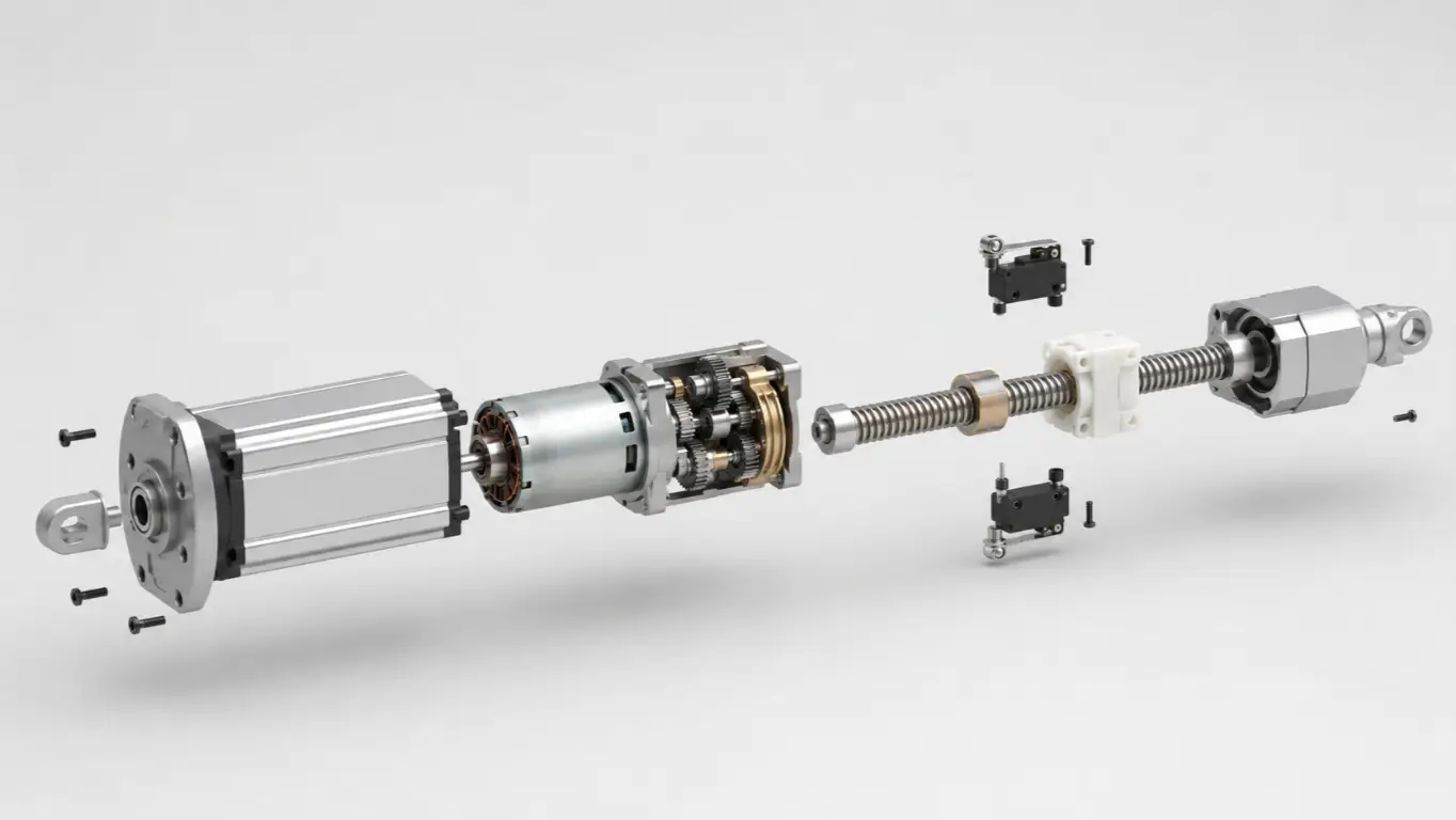
Axial Force, Side Load, and Moment: The Three Forces Your Actuator Actually Feels
A linear actuator is designed for one job: pushing and pulling along its axis. It is not a guide rail. It is not a structural support. Any force that lands perpendicular to the actuator rod — a side load from an off-center weight, or a moment from a misaligned mounting bracket — lands on the internal bearings. These bearings are typically bushings designed for axial loads only.
A typical industrial actuator can handle a side load of just 5–10% of its axial force rating. Even a 1–2° mounting misalignment generates a side force component that, while small in absolute terms, creates concentrated contact stress inside the bearing far beyond what it can sustain over repeated cycles. When an actuator fails prematurely and the force calculation was “correct,” side loading is the culprit far more often than undersized thrust.
The rule is absolute: if your load applies any force that is not directly in line with the actuator rod, you need an external linear guide to absorb it. The actuator pushes and pulls. The guide handles everything else.
Calculating Force by Mounting Type: A Practical Framework for Every Application
Every force calculation starts with the same physics, but your mounting geometry determines which forces dominate and which trap you are most likely to fall into. Use this framework to identify your application type, then apply the formula that matches your actual geometry, not the simplified textbook case.
Vertical Lifting: The Simplest Case, With One Trap Everyone Misses
A vertical lift seems straightforward: the actuator must overcome gravity, so F = m × g (where g = 9.81 m/s²). But that gives you the minimum — the force to hold the load stationary. To actually lift it, you need more.
The complete formula:
Ftotal = m × g + Ffriction + m × a
Where Ffriction accounts for seal drag inside the actuator and any guide friction, and m × a is the acceleration force. Many first-time specifiers forget the acceleration term, and it is precisely what causes the actuator to stall at the bottom of the stroke.
Worked example: You need to lift a 100 kg platform vertically at 0.2 m/s² acceleration.
- Gravity: 100 × 9.81 = 981 N
- Estimated friction (seals + guides): ~15 N
- Acceleration: 100 × 0.2 = 20 N
- Total: 1,016 N
With a 1.5× safety factor, select an actuator rated at ≥ 1,524 N. A 1,500–2,000 N model is the right ballpark. Had you only calculated gravity (981 N), you might have chosen a 1,200 N unit and wondered why it struggled to start.
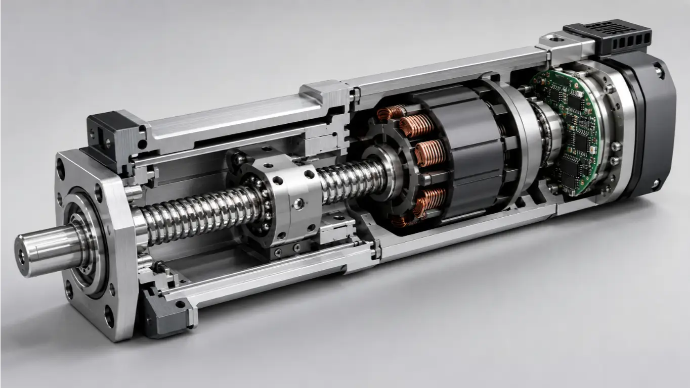
Also note: lead-screw actuators are typically self-locking, so the load will not back-drive when power is removed. Ball-screw actuators are not. If you are lifting something that must stay up when unpowered, choose a lead screw or add a brake.
Horizontal Push/Pull: Friction Is Your Real Opponent
In a horizontal application, gravity works perpendicular to motion, so it does not directly add to your force requirement. Instead, friction becomes the dominant term.
The formula:
Ftotal = μ × m × g + m × a
Where μ is the coefficient of friction between your load and its bearing surface.
Worked example: A 200 kg steel slide table on steel rails, accelerating at 0.3 m/s². The steel-on-steel friction coefficient (unlubricated) is around 0.15.
- Friction: 0.15 × 200 × 9.81 = 294 N
- Acceleration: 200 × 0.3 = 60 N
- Total: 354 N
With a 1.5× safety factor: 531 N. A 600 N actuator would be appropriate.
Now here is the trap: μ is not a constant. That 0.15 assumes clean, dry, perfectly aligned steel surfaces. If the rails are slightly misaligned, if there is dust or contamination, or if lubrication has degraded, μ can easily double or triple. Linear ball-bearing guides have catalog friction coefficients as low as 0.002–0.005, but installation misalignment can degrade them by a factor of 5–10×. When in doubt, measure the actual push force on your prototype. A $50 force gauge can save you a $500 actuator replacement.
Angled Mounting: Why Your Force Requirement Just Got Bigger
When an actuator pushes at an angle to the direction of load motion, only the force component parallel to the motion does useful work. The perpendicular component is wasted. The shallower the angle, the more force is wasted.
The formula:
Factuator = Fload / sin(θ)
Where θ is the angle between the actuator rod and the load’s direction of motion. At 90° (actuator pushing straight in line with the load), sin(90°) = 1, and Factuator = Fload — the ideal case.
How angle multiplies your force requirement:
| Angle (θ) | sin(θ) | Force Multiplier |
|---|---|---|
| 90° (ideal) | 1.000 | 1.00× |
| 60° | 0.866 | 1.15× |
| 45° | 0.707 | 1.41× |
| 30° | 0.500 | 2.00× |
| 15° | 0.259 | 3.86× |
At 45°, you need 41% more actuator force. At 30°, you need double. At 15°, nearly four times. And because the actuator extends and retracts, the angle changes through the stroke. Calculate using the worst angle, not the average.
Worked example: A 50 kg hatch door lifted at a 30° angle relative to the actuator rod.
- Fload = 50 × 9.81 = 490 N
- Factuator = 490 / sin(30°) = 490 / 0.5 = 980 N
Compare that to a vertical lift of the same load: 980 N vs. 490 N. The 30° angle doubled the requirement. If the angle tightens to 20° mid-stroke, the force spikes to 490 / sin(20°) = 1,433 N. Always calculate across the full stroke and size for the peak.
Hinged and Pivoting Applications: The Worst-Case Position Rule
This is where most sizing mistakes happen and where the consequences are most expensive.
In any hinged application (hatches, lids, gates, solar panel tilt mechanisms), the actuator creates torque around a pivot. The required actuator force depends on the perpendicular distance from the actuator’s line of action to the pivot — the moment arm. And that moment arm changes continuously through the stroke.
The formula (torque balance):
Factuator = (m × g × dload) / dactuator
Where dload is the horizontal distance from the pivot to the load’s center of mass, and dactuator is the perpendicular distance from the pivot to the actuator’s line of action.
The trap: In the closed position, the actuator arm is nearly parallel to the door. The moment arm is at its minimum. This is where the force requirement peaks.
Worked example: A 130 kg steel equipment cover, hinged at one end. The center of mass is 0.5 m from the hinge. In the fully closed position, the actuator’s moment arm is just 0.05 m.
- Factuator = (130 × 9.81 × 0.5) / 0.05 = 637 / 0.05 = 12,740 N
Now open the cover to 60°. The moment arm lengthens to 0.15 m:
- Factuator = 637 / 0.15 = 4,247 N — less than one-third of the closing force.
This pattern shows up across engineering applications. One documented case on a lifting mechanism required 23,833 N at a 30° boom angle, a 36× increase from the force needed near the fully open position (Engineering Stack Exchange, 2023).
The rule: Always size your actuator for the worst-case position in the stroke. That is almost always the fully closed or fully retracted position, where the moment arm is shortest. Do not average. Do not use the mid-stroke geometry. Use the hardest-to-move position.
Beyond the Textbook: Four Real-World Factors That Multiply Your Force Requirement
The basic formulas above give you a theoretical force number. But between your spreadsheet and the factory floor, four factors routinely multiply the real requirement by 2–5×. None of them appear in most sizing guides. Address these before you place an order, or you will address them after the actuator fails.
The Friction Amplification Problem: Why Real-World Friction Is 5–10× Higher Than You Expect
Catalog friction numbers assume perfect alignment, clean surfaces, proper lubrication, and controlled temperatures. Your installation has none of those guarantees.
A documented case from industrial machinery shows the scale of the problem. A 13,000 lb paper mill roll stand, on what was assumed to be a level floor, experienced 113 lbf of unaccounted force simply because the floor had a 0.5° slope (Web Guide Actuator Sizing Engineering Reference, 2024). That 113 lbf exceeded the combined textbook friction and inertia forces. Cable drag chains, hose bundles, and wiring harnesses — the “umbilical” forces that CAD models ignore — routinely add 15–60 lbf per bundle in industrial installations.
The sources of friction amplification stack:
- Mounting misalignment (most severe): linear guides rated at μ = 0.002–0.005 can degrade to an effective μ of 0.01–0.05 when mounting surfaces are not parallel — a 5–10× increase.
- Contamination: dust, moisture, and process debris increase sliding friction within days of commissioning.
- Lubrication degradation: factory-applied grease thins at elevated temperatures and oxidizes over time.
- Thermal expansion: differential expansion between the actuator body and its mounting structure introduces preload forces.
One practical mitigation: before committing to hardware, measure the actual breakaway force on your prototype with a force gauge. The number will almost certainly be higher than your calculation. The difference tells you how much margin you really need.
Safety Factors: Why 1.5× Is Not a Magic Number
“Apply a 1.5× safety factor” is the most common advice in actuator sizing guides — and the laziest. The right safety factor depends on what you know about your load, and what happens if your actuator fails.
| Application Profile | Recommended Safety Factor | Rationale |
|---|---|---|
| Predictable load, controlled environment | 1.25–1.5× | Low uncertainty; small margin covers manufacturing tolerances |
| Variable load, moderate environmental variation | 1.5–2.0× | Covers unknown-but-bounded load fluctuations |
| Shock or impact loads present | 2.5–3.0× | Peak forces from impact can reach 2–10× the static load |
| Personnel safety involved (medical lifts, accessibility platforms) | 3.0–5.0× | Failure consequences are unacceptable; regulatory requirements often mandate 4× minimum |
| Unknown or poorly characterized load | 3.0–5.0× | Margin substitutes for missing data |
The logic is straightforward: a safety factor is insurance against what you do not know. If you have instrumented your prototype and measured peak forces across the full stroke, 1.25× may be adequate. If you are estimating friction from a textbook table, build in more margin.
For medical and accessibility applications, European Machinery Directive requirements commonly mandate a minimum safety factor of 4× against yield. This is not optional over-engineering; it is regulatory compliance.
Duty Cycle and Force Derating: When Your Actuator Needs to Keep Working
Most actuator force ratings assume intermittent operation — a few minutes of running followed by a long rest period. If your application requires continuous or near-continuous motion, the story changes.
Duty cycle is defined as:
Duty Cycle (%) = (Running Time / (Running Time + Rest Time)) × 100%
A 10% duty cycle means the actuator runs for 2 minutes, then rests for 18. At 100% duty cycle, it runs continuously.
As duty cycle increases, heat builds up in the motor windings. Winding resistance rises with temperature, torque output drops, and the available force declines — even though the actuator’s nameplate rating has not changed.
Approximate force derating by duty cycle (varies by motor design and cooling; use manufacturer curves when available):
| Duty Cycle | Available Force (% of rated) |
|---|---|
| 10% | ~100% |
| 25% | ~85% |
| 50% | ~65% |
| 100% (continuous) | ~50% |
At 50% duty cycle, your 2,000 N actuator may only deliver around 1,300 N. At continuous operation, around 1,000 N. If you sized for 1,500 N at 10% duty cycle but the application actually runs at 40%, you are in trouble.
What to check: If your application runs more than 2–3 minutes at a time, look at the actuator’s force-speed curve instead of its headline force number. The power relationship — P = F × v — means you trade speed for force at a given motor wattage. A faster actuator delivers less force. A higher-force actuator runs slower. You cannot maximize both.
Side Loads and Moment Forces: The Silent Actuator Killer
If an actuator fails within months of installation and the thrust calculation was correct, side loading is almost always the answer.
Side loads come from anywhere the load is not perfectly centered on the actuator rod axis: an off-center mounting point, a load whose center of mass shifts during motion, an installation bracket welded 2 mm out of position. These generate a bending moment inside the actuator tube. The internal slide bushings, designed for axial sliding only, see concentrated contact stresses far beyond their material limits.
The side force from an offset load:
Fside = Fload × (doffset / Lguide)
Where doffset is the distance from the load’s center of mass to the actuator axis, and Lguide is the length of the external linear bearing or guide supporting the load.
The non-negotiable rule: the actuator rod must not act as the guide rail. If your load can wobble, tilt, or drift off-axis during motion, install external linear guides — rods, rails, or slides — that carry the side loads and leave the actuator to do its one job: push and pull along its axis.
From Calculation to Selection: Making Your Force Number Work in the Real World
You have calculated a force — say, 850 N after safety factors. Now you need to turn that number into an actuator order. Three quick checks will keep you out of trouble:
1. Force match — derate before you select. Real-world available force is typically 60–80% of rated force. To deliver 850 N reliably, look for an actuator rated at roughly 1,100–1,400 N, not 900 N.
2. Speed check — use the force-speed curve. Actuators slow down as load increases. A unit rated at 20 mm/s may drop to 10–14 mm/s near its maximum force. Confirm that your required speed is achievable at your calculated force, not at zero load.
3. Environment match. Is the installation dusty, wet, or outdoors? An IP54 rating handles dust and splashes. IP65 handles water jets and is a safer bet for outdoor equipment. If the environment is hazardous (flammable gases or dust), you may need an explosion-proof certified actuator — a requirement that eliminates most standard models.
If your calculated force, speed, and environmental requirements do not line up neatly with any off-the-shelf model, that is not unusual. Standard catalogs cover common combinations; real applications rarely fit them perfectly. Hoodland, a linear motion manufacturer with in-house R&D and mold-making capabilities, offers custom actuator engineering support spanning 20 N to 6,000 N of force, 25 mm to 2,000 mm of stroke, and IP ratings up to IP65 — all configured within a single build, with no minimum order quantity. For applications that fall between catalog lines, working with a manufacturer that controls the full engineering stack can turn a “close enough” selection into an exact fit.
When the Numbers Don’t Add Up: Troubleshooting Actuator Force Problems
You calculated the force. You selected the actuator. You installed it. And it does not work right. Here are the five most common force-related failure modes and how to diagnose them:
Most of these failures trace back to one root cause: the force calculation assumed ideal conditions that the installation did not provide. Measure your actual forces, verify your geometry at every position in the stroke, and do not trust a single textbook number without testing it.
If your application involves unusual mounting geometry, high duty cycles, or safety-critical loads, a 30-minute engineering review of your force calculations can prevent a field failure. The difference between a correctly sized actuator and a close-enough guess often shows up not on day one, but at cycle 8,000 — when the undersized unit overheats for the last time and your production line stops. The review costs a fraction of that downtime.