
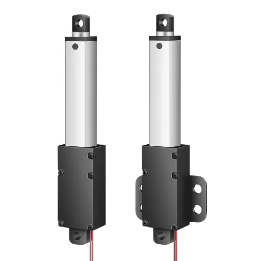
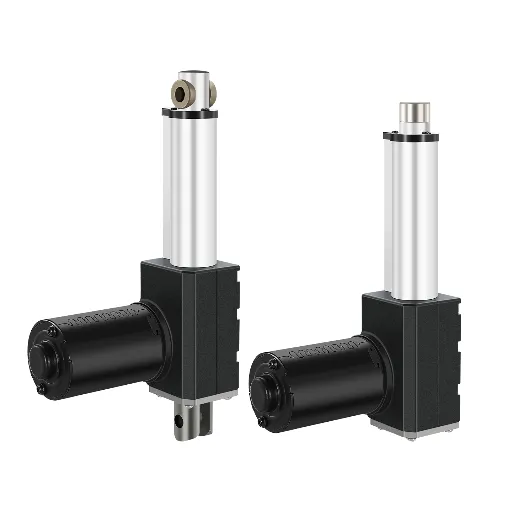
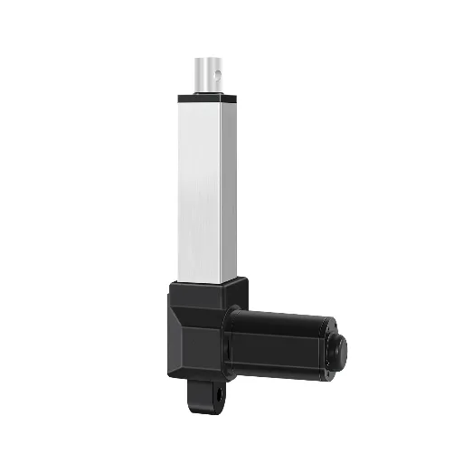
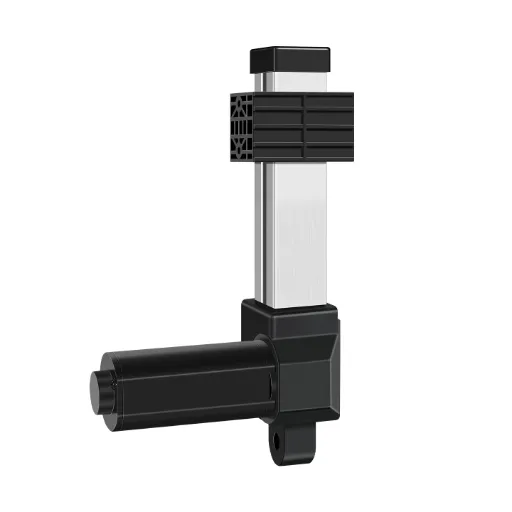
First, Count the Wires: What Those Wires Actually Do
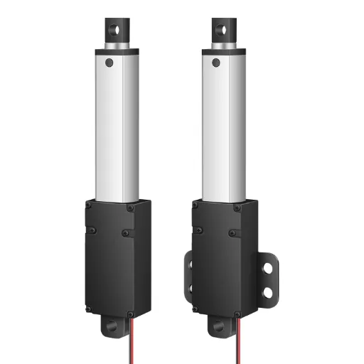
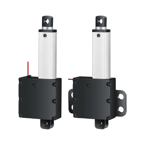
Before you match any color to any terminal, count the wires. That single step prevents most of the confusion you will find in a typical “linear actuator wiring diagram” search, because wire colors are not standardized across manufacturers, and never have been. Red is not always positive. Black is not always negative. What every actuator shares is structure: a small DC motor turns a lead screw, and the nut on that screw becomes the rod you see extend and retract. Reverse the polarity and the motor spins the other way, so the rod comes back. That is the whole mechanism.
One clarification before we go further. If you searched “5 wire actuator wiring” because of a car door lock, stop here, because door lock motors use a different control logic entirely. This article is about linear actuators: screw-driven push/pull devices controlled by reversing DC power.
Two wires in any actuator cable are always the motor’s power pair, and they are always the thickest wires in the bundle. Everything thinner than those is a signal wire: feedback, limits, or sensors. So the recognition routine is three steps:
- Count the wires.
- Separate the thick pair from the thin rest.
- Verify with a multimeter (continuity across the thick pair = motor coil; resistance or voltage change on the thin wires = feedback).
Match the voltage before anything else. A 12 V actuator on 24 V can burn the motor and the limit switches; a 24 V actuator on 12 V simply won’t move. And a transformer’s AC output will not drive a DC actuator: you need a DC power supply or a rectifier. This is the most common first mistake in every wiring failure thread we’ve collected.
The Wire-Count Ladder: 2-Wire to 8-Wire
The number of wires is the number of information channels: two for motor power, and everything after that is communication. Walk up the ladder and each rung adds one capability, and one thing that can be wired wrong.
2–3 Wires: Power vs. Signal
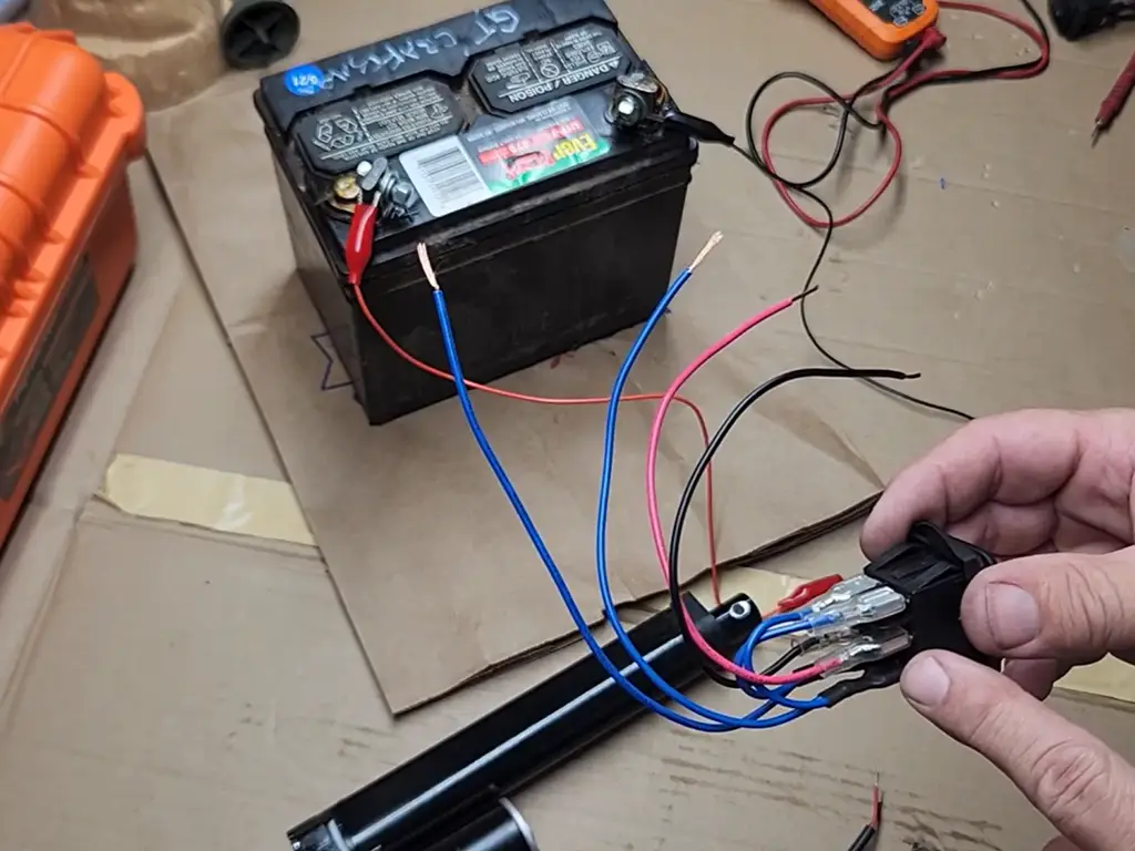
A 2-wire actuator is motor-only: extend with +12 V on red and − on black, retract by swapping. Direction wrong? Swap the leads. That’s the entire diagram.
A 3-wire actuator adds one signal wire, usually one limit switch, or a shared common for a feedback pair. The rule that matters here: never route motor current through the thin signal wire. It is sized for milliamps, not amps, and it will melt.
4–5 Wires: Where Feedback Comes From
A 4-wire unit is typically motor plus two limit switches (fully extended / fully retracted), or motor plus a two-wire potentiometer. Both tell your controller where the rod is, in different languages.
⭐ The 5-wire layout is the one you will meet most often in equipment with any kind of control: two thick power wires plus three thin feedback wires. But the point nearly every online guide glosses over: “5-wire” is not one thing. The three thin wires can be limit switches, a Hall sensor, or a potentiometer, and each is wired and read differently. We’ll unpack that in the next section.
8 Wires: The Full Feedback Stack
A few industrial units carry the full set: motor, dual limits, potentiometer, and a ground/shield. They exist so one cable can feed everything a machine controller needs. If you find one with an unlabeled 8-wire bundle, don’t guess. Trace every conductor with a multimeter before powering anything. This is exactly the scenario where buyers on robotics forums end up stuck, because no color chart covers it.
| Wires | What’s inside | What it can do | Typical use | Where it fails |
|---|---|---|---|---|
| 2 | Motor only | Extend / retract by polarity | Simple lifts, DIY | Nothing to protect against overtravel |
| 3 | Motor + 1 signal | One end-of-travel signal | Basic limit detection | Signal wire mistaken for power → melt |
| 4 | Motor + 2 limits, or motor + pot | Both ends reported, or continuous position | Furniture, gates | Limits report “reached” not “where” |
| 5 | Motor + 3-wire feedback | Limits, Hall, or potentiometer position | Controlled equipment, machines | Feedback type guessed wrong → wrong signals |
| 8 | Motor + full feedback stack | Everything above | Industrial integration | Identification; trace before powering |
Manufacturer manuals confirm the inconsistency: some document 5-core feedback as Hall sensor or potentiometer wiring, others as limit-switch wiring, with different color schemes in each (HIWIN Linear Actuator User Manual; FLINA/Metra actuator wiring PDF). That is why identification comes first, always.
Picking a Control Scheme: Direct, Relay, Control Box, or PLC
Once you know what your wires are, the next decision is what sits between the power source and the actuator. There are four common schemes, and the right one depends on current, duty, and how automated the system needs to be.
| Control scheme | When it works | When it doesn’t |
|---|---|---|
| Direct connection (momentary test) | Bench testing, verifying direction | Any real install: no stop, no protection |
| Rocker / DPDT switch | Low current, human-operated | High current (switch contacts overheat); remote control |
| Relay(s) (SPDT/SPCO) | High current, remote buttons, moderate automation | Needs limit switches or timer for auto-stop; relay contact rating must exceed motor current |
| Control box + handset | Multi-actuator (desks, beds), limits + feedback + smooth ramp | Non-standard functions need a custom controller |
| PLC / controller input | Production machines, feedback integration | Overkill for a single manual lift |
The decision rule is simple: if the switch’s contacts are rated below the motor’s running current, or you want to stop at limits automatically, add relays. If you need two actuators moving together, or limit and feedback signals handled cleanly, a control box does what a pile of relays would. If the actuator is one axis in a machine, it feeds your PLC’s digital or analog inputs directly.
One trend is worth noting: feedback-equipped actuators now have their own category on every major actuator e-commerce site, and control boxes are creeping down from industrial gear into furniture and home automation. Position feedback, once a “limit switch tells you it’s done” affair, is becoming a standard expectation, and remote/IoT control is following. If you’re designing a product for a 5-year lifecycle, wire it as if a controller will be attached, even if day one is a switch.
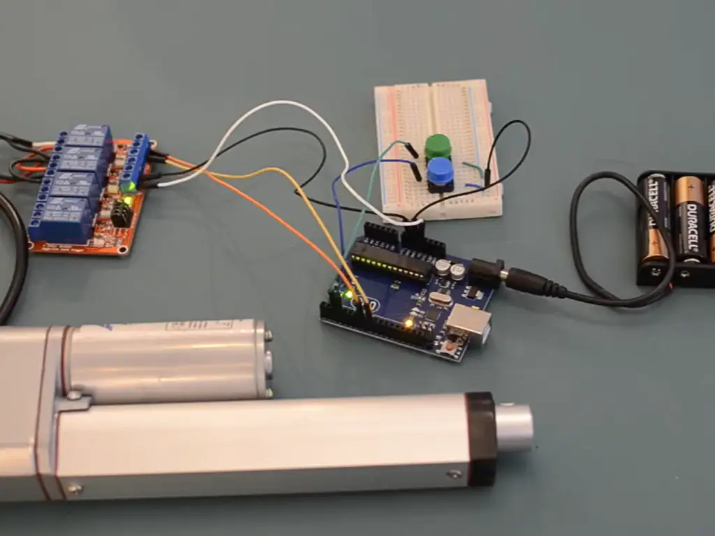
Watch: How to control a linear actuator with 12V DC relays
This wiring walkthrough shows how the power supply, rocker switch, relays and actuator connect together.
Wiring a 5-Wire Actuator: Identify the Feedback First
Identify before you wire
Every 5-wire actuator carries two power wires and three feedback wires. The feedback can be limit switches, a Hall sensor, or a potentiometer — identify the type before you wire anything, because colors are not standardized and each type wires differently.
Step 1: Identify the Feedback Type
Here is the practical test for each of the three types:
- Limit switches: two thin wires that close a circuit at each end of travel, plus a common. Test with a multimeter in continuity mode while moving the rod by hand. You should hear the meter beep at full extension and full retraction.
- Hall sensor: a small solid-state sensor that outputs a level signal (or a proportional signal on linear Hall types) as the rod moves. Test by measuring voltage on the signal wire while moving the rod: it switches or ramps without mechanical contacts.
- Potentiometer: the most common feedback design is a 10 kΩ three-wire system, where a wiper voltage changes proportionally with position (Firgelli FA-PO feedback rod actuator; RS Components actuator datasheet). Measure resistance between the wiper and either end while moving the rod: it sweeps smoothly.
Every manufacturer documents these differently. One 5-wire guide presents thick red/blue power with thin red/black/green limits (ActuLift 5-wire guide); another’s manual describes 5-core Hall and potentiometer layouts on different terminals (HIWIN manual). Same wire count, different meanings. This is why identification by testing beats identification by color chart, every time.
Step 2: Connect Power and Signal
Connect the thick pair to your power source. Polarity decides direction; swap to reverse. Then bring the three thin wires to your controller:
- Limit switches → digital inputs (they’re switch closures to common).
- Potentiometer → analog input (it’s a voltage divider; share the controller’s ground).
- Hall sensor → digital input or encoder-style input, depending on output type.
Whatever the type, the thin wires carry milliamps. Feeding motor current through them is a one-way ticket to melted insulation and a dead feedback circuit.
Never guess the feedback type from wire color alone. Three manufacturers’ documents we verified disagree on what a “5-wire” bundle contains. A limit-switch unit wired as a potentiometer reads garbage on the analog input, and your controller never knows where the rod is. Thirty seconds of continuity testing prevents an hour of “why is the signal wrong?”
Step 3: Size the Wire, Fuse, and Connector
Motor current decides the wiring, not the other way around. NEC Table 310.15(B)(16) rates 16 AWG copper at 10 A (60 °C column) and 18 A at 90 °C, so 16 AWG is a reasonable floor for most 12 V actuators, with 14 AWG for heavier units or long runs (Cerrowire ampacity charts). Put a fuse on the positive lead as close to the power source as possible. A 3 A fuse suits a small actuator; size it above running current but below stall current, since a stalled motor can draw several times its running current. On long cable runs, voltage drop matters more than ampacity: extend the run and you may need to step up a gauge to keep speed consistent.
| Feedback type | Signal it produces | Best for | Where it stops working |
|---|---|---|---|
| Limit switches | Contact closure at each end | Simplicity, cost, absolute end detection | No intermediate position; mechanical wear over cycles |
| Hall sensor | Digital or proportional level | Medium precision, speed sensing, no wear | Needs supply voltage; signal integrity in noisy runs |
| Potentiometer | Analog wiper voltage (10 kΩ typical) | Continuous position feedback | Wiper wear; nonlinearity on long strokes; needs analog input |
Connectors deserve the same attention as wire gauge. A pre-wired connector (automotive-style, waterproof, or a custom pinout) turns “field wiring by whoever is on site” into “plug it in.” If the cable length, connector, and pinout are specified at ordering time, they arrive consistent. Consistent wiring is what kills the largest share of field failures.
What to Ask a Supplier About Wiring Before You Buy
Everything above has one practical consequence: wiring information is a supplier capability, not a manual you hunt for later. If colors aren’t standard and feedback types vary, the supplier who documents their own wiring is the supplier who saves you the failure hunt.
Before you order, run this five-question check on the supplier:
If a supplier hesitates on any of these, you are buying a wiring mystery along with the actuator. If they answer all five, the diagram for your unit is the deliverable, not a scavenger hunt.
If It Doesn’t Move: Diagnosing Wiring Failures
When a freshly wired actuator does nothing, the wiring is the prime suspect, and usually the culprit. Work in a fixed order: power first, signal second.
| Symptom | Most likely cause | Check this |
|---|---|---|
| Nothing moves | No power / wrong polarity / blown fuse | Voltage at the actuator terminals; fuse; swap the two power leads |
| Moves the wrong way | Polarity reversed | Swap power leads: no damage done |
| Intermittent / twitchy | Loose connection, undersized wire, long run | Torque the terminals; measure voltage under load; step up a gauge |
| Limits never trigger | Wrong feedback type assumed, signal on wrong input, no common ground | Continuity test the thin wires; confirm limit vs. potentiometer; share ground |
| Fuse blows instantly | Short circuit, stall, thin wire overloaded | Inspect cable for crushed spots; check stall; verify wire gauge |
Real cases from the wiring threads
If the power side is verified and signals are correct but behavior is still wrong, the fault has moved inside the actuator: worn limit switches, a damaged feedback pot, or controller settings. That’s the point to take the supplier’s troubleshooting guide (and their support) seriously.
Why Wiring Specs Belong in Your Procurement Sheet
Step back from the workbench for a moment. This article has established three facts: 5-wire feedback comes in three different types, wire colors are not standardized across manufacturers, and wiring failures are the most common first-failure entry point in real installs. For anyone building actuators into a product, a bed, a workstation, a machine axis, those facts have a direct business meaning.
Every supplier change or new batch means re-walking the whole wiring pit.
A new supplier’s “5-wire actuator” may carry different feedback, different colors, different connector expectations. Your drawings change, your field technicians re-learn, your support line takes the calls. And a feedback type chosen wrong at order time isn’t a “minor wiring thing”: it’s a functional defect that shows up at commissioning, the most expensive moment to find it.
| Procurement spec item | What to require |
|---|---|
| Feedback type | State explicitly (limits / Hall / potentiometer), never leave implied |
| Wire colors & gauge | Locked to your BOM, consistent across batches |
| Cable length | Specified at order, not trimmed in the field |
| Connector | Pre-wired, waterproof if needed, pinout documented |
| Wiring documentation | Supplied with each unit, for that unit |
| Change control | Written notice before any wiring change on reorders |
Suppliers who can answer this card, and put the answers in the box with the actuator, are the ones whose wiring will never be a surprise on your line.
And if you’d rather specify those details at order time than discover them at install time, Hoodland builds wiring specs like cable length, connectors, and feedback type into the unit you order, so the diagram arrives with the part.
Lock the Wiring Spec Into the Order
Cable length, connectors, and feedback type specified at quote time ship with the unit — so the diagram arrives with the part.
Request a QuoteReferences
- Cerrowire. “Ampacity Charts / Wire Gauge Chart (NEC Table 310.15(B)(16)).” https://www.cerrowire.com/products/resources/tables-calculators/ampacity-charts/
- Firgelli Automations. “FA-PO Series: Precision Feedback Rod Actuator (10K ohm 3-wire potentiometer feedback).” https://www.firgelli.com/products/feedback-rod-actuator
- RS Components. “Linear Actuators datasheet (potentiometer absolute positioning feedback, 10K ohm).” https://docs.rs-online.com/a72f/0900766b8168345d.pdf
- HIWIN. “Linear Actuator User Manual (5-core Hall sensor and potentiometer feedback wiring).” https://hiwin.sg/wp-content/uploads/2020/08/Linear-Actuator-User-Manual.pdf
- Metra (FLINA). “Linear Actuators Wiring Diagram (potentiometer reference wiring).” https://metra-static.s3.amazonaws.com/documents/Linear_Actuator_Wiring.pdf
- ActuLift. “How to Wire a 5-Wire Linear Actuator (Step-by-Step).” 2026. https://actulift.com/how-to-wire-a-5-wire-linear-actuator/
- All About Circuits forum. “12v linear actuator wiring diagram – TV bed lift project.” 2018. https://forum.allaboutcircuits.com/threads/12v-linear-actuator-wiring-diagram-tv-bed-lift-project.154447/
- Reddit r/robotics. “I got a 24v dc linear actuator with 5 wires.” 2018. https://www.reddit.com/r/robotics/comments/8lq6wj/i_got_a_24v_dc_linear_actuator_with_5_wires/
- Reddit r/robotics. “Found this linear actuator, it has 8 wires plus a ground.” 2021. https://www.reddit.com/r/robotics/comments/oxery7/found_this_linear_actuator_it_has_8_wires_plus_a/
- Reddit r/askanelectrician. “Linear Actuator / Limit Switch Wiring – Help!” 2020. https://www.reddit.com/r/askanelectrician/comments/km53fn/linear_actuator_limit_switch_wiring_help/
- Hoodland. “Custom Solution.” https://www.thehoodland.com/custom-solution/
- Hoodland. “Installation Guide.” https://www.thehoodland.com/installation-guide/
- Hoodland. Homepage. https://www.thehoodland.com/
 English
  Chinese