
Linear vs Rotary Actuator: Why “Which Is Better” Is the Wrong Question
Ask what separates a linear actuator from a rotary one and you will get a definition: the linear type pushes and pulls along a straight line, the rotary type turns something around an axis (MOONS, 2024). That definition is true, but it hides the part that matters. So let’s start there.
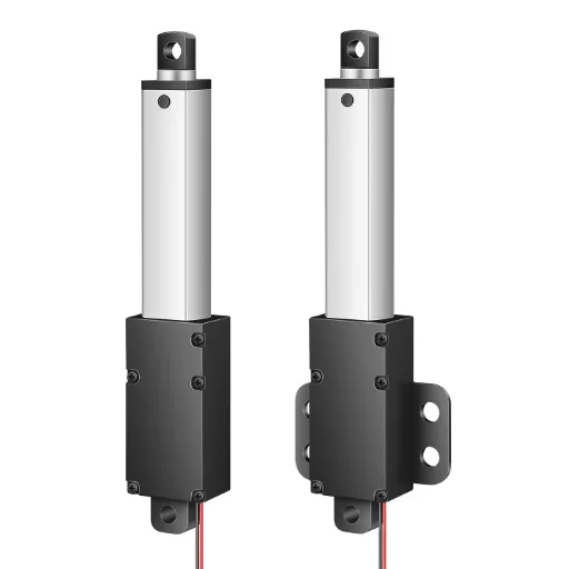
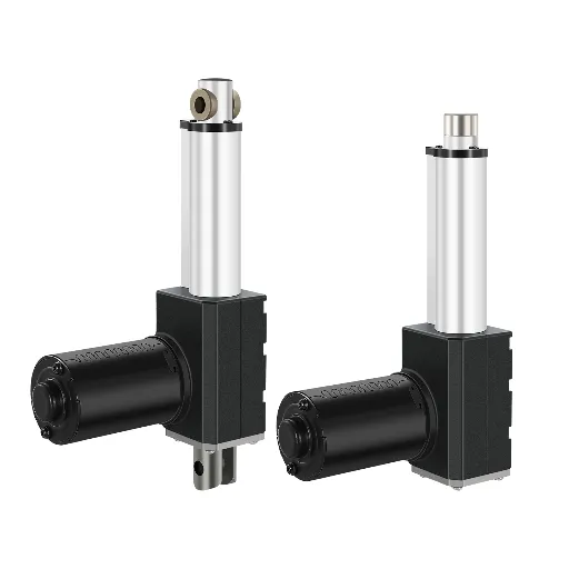
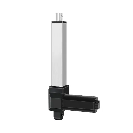
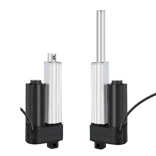
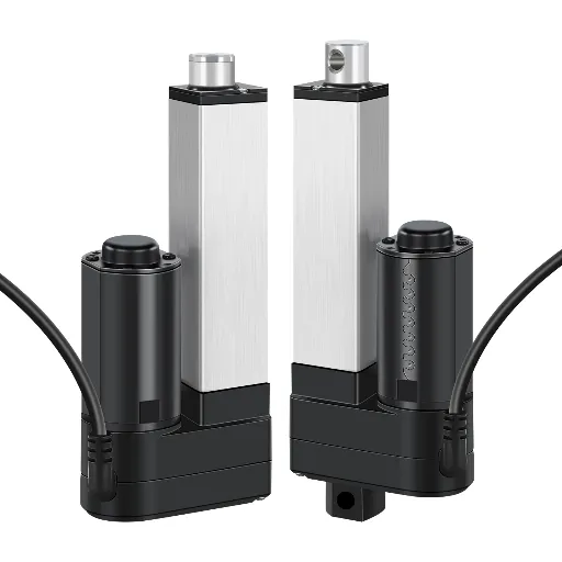
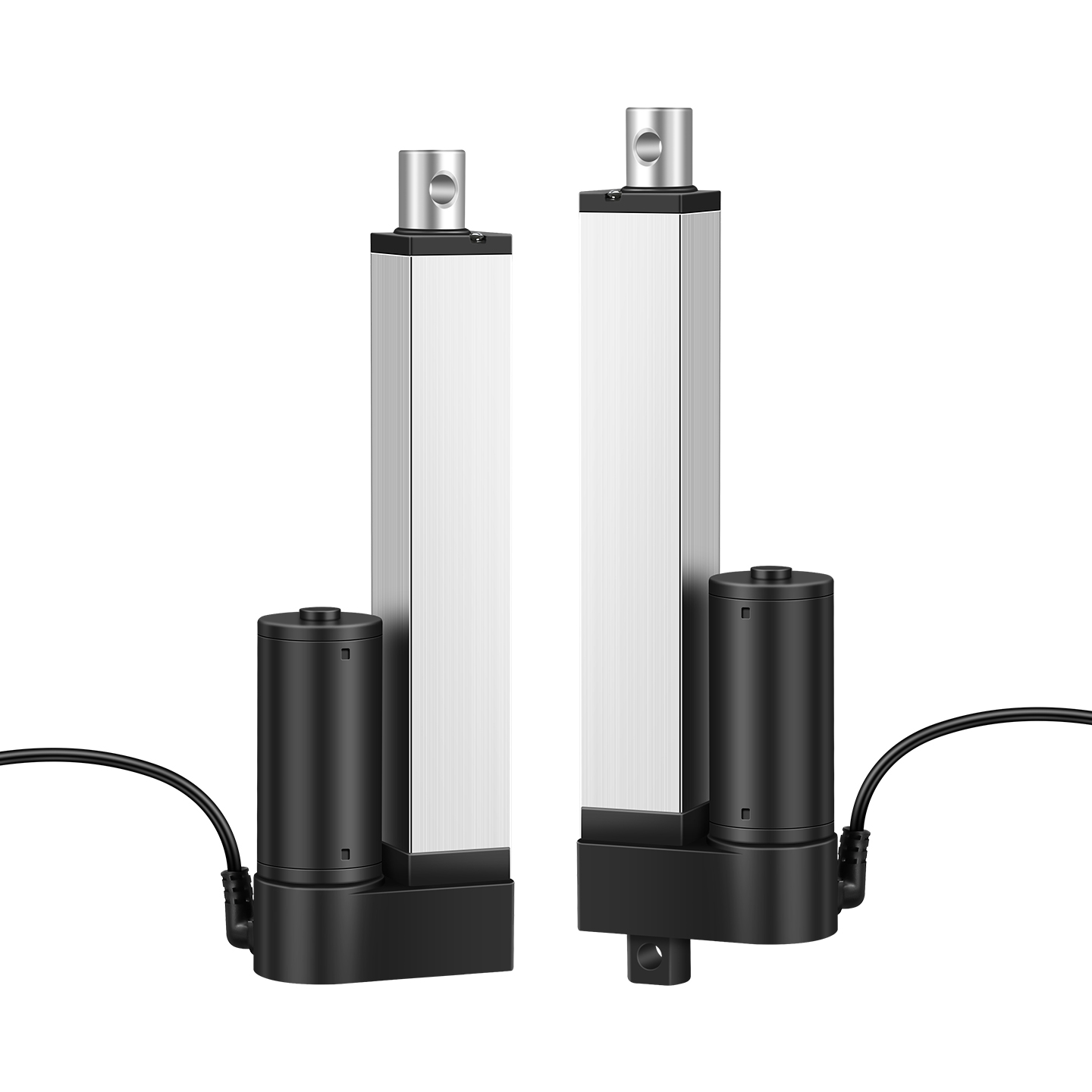
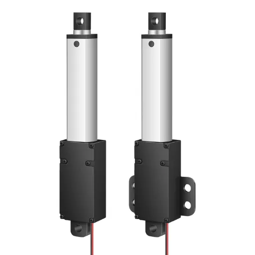
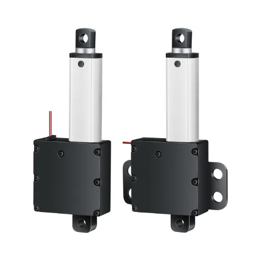
A typical electric linear actuator is a rotary motor with a screw or a worm gear bolted to its output. Everything after that is engineering choices.
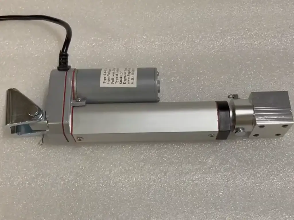
Keep that sentence. It is the key to this whole topic. Inside an electric linear actuator, a DC motor spins, and a threaded screw (or a worm gearbox) converts that rotation into the push-pull motion of a rod. The “linear” part is not a new kind of machine. It is a rotary motor plus a conversion mechanism, packaged into one housing. A rotary actuator, by contrast, outputs rotation directly: a shaft that spins a wheel, a lever, a damper vane, or a quarter-turn valve.
Rotary in, linear out
Rotary motor spins
Screw or worm gear converts rotation
Rod extends / retracts in a straight line
Linear motion output
That single fact explains most of what confuses people about this comparison. When someone says “rotary actuators are cheaper,” what they usually mean is “a motor with a lever and a rod is cheaper than a packaged screw-driven unit.” Both statements are true, because they are about different things. The comparison only makes sense once you look at the mechanism, which is what this article does.
One naming trap before we go further: the word “actuator” is used in two different worlds. In valve automation, a “linear valve actuator” drives a rising-stem valve and a “rotary valve actuator” drives a quarter-turn (ball or butterfly) valve. Those are valve attachments with their own interface standards. In motion control, “linear” and “rotary” describe the output of the drive itself. This article is about the second world, and it applies to electric actuators. Pneumatic and hydraulic actuators follow the same split, but their trade-offs come from the power source, not the mechanism.
The one-sentence version
Everything after that is engineering choices.
How Linear Motion Is Made: Screws, Worm Gears, Linkages and Belts
Once you know that a linear actuator is “rotary motor + conversion mechanism,” the obvious next question is: which mechanism? Because the mechanism decides everything: precision, efficiency, noise, self-locking, and cost. This is also the question that forums argue about, usually without naming the mechanism.
Lead Screws and Ball Screws: Precision at a Price
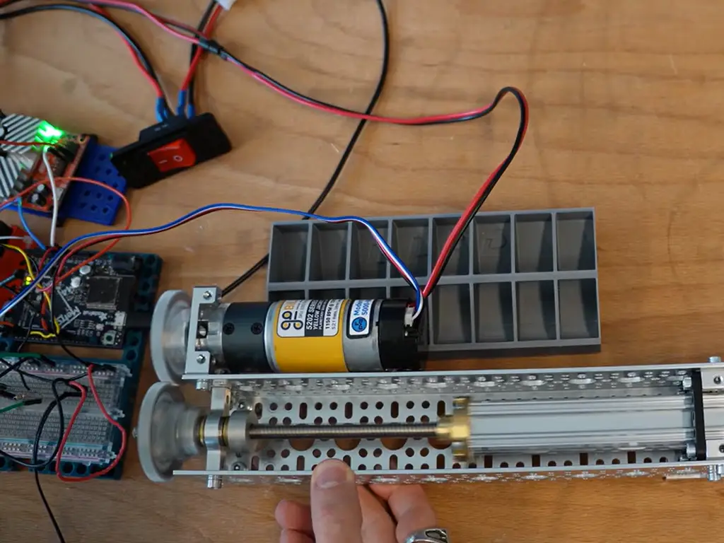
A lead screw is a threaded rod; a nut rides on it as it turns. Lead screws are the workhorses of electric linear actuators. They are simple, self-locking, and quiet enough for indoor equipment. Their catch is efficiency. Sliding friction burns a large share of the input power; a ball screw gets roughly 90% efficiency out of the same motor, and a lead screw runs well below that (Thomson Linear).
A ball screw replaces sliding friction with recirculating steel balls. It runs 90%+ efficient, smooth, and precise, and it converts motor torque into thrust better than any lead screw. What it gives up is equally important: a ball screw is not self-locking. Under a vertical load, it will back-drive, so the design must add a brake or a holding brake (PBC Linear). Ball screws also cost more and run noisier than lead screws (Thomson Linear). That is a real issue in medical or bedroom-adjacent applications.
Worm Gears: Quiet, Self-Locking, and Inefficient
A worm gear drives a wheel at a right angle with a huge reduction ratio, which makes it a favorite for compact actuators. It is quiet, it is self-locking (the worm wheel cannot drive the worm back), and it multiplies torque. The price: efficiency. Worm-driven units convert a large share of input power into heat, far below the 90% of a ball screw. That is why they heat up under sustained duty cycles.
Worm gears are also the source of the backlash complaints you read on motion-simulation forums. A worm drive needs clearance for lubrication, and that play shows up as slop in the output. One long-running community thread on switching from linear to rotary actuators in motion platforms puts it directly. A rotary approach “relies on the bolt-on gearbox, an attached lever and pot/hall sensor” and is “simpler and much cheaper.” The worm drive’s “play for lubrication purposes” is exactly why the linear unit felt tighter (xsimulator.net). Neither side is wrong. They are describing different mechanisms.
Backlash is running clearance, not a defect. Every worm drive needs a little play to run. What matters is how much of it reaches the rod — that is what separates a precision build from a cheap one.
Linkages and Belts: Cheap, Simple, and a Little Sloppy
The cheapest way to make linear motion is to not convert it at all: bolt a lever to a motor shaft and push the load with the free end. A crank-and-connecting-rod or a belt drive does the same job at low cost with very few parts. That is the “rotary actuator” solution in motion platforms and many hobby builds, and it explains why rotary-based designs often cost less.
The trade-off is geometry. A linkage does not produce constant speed or constant force along its travel. It accelerates and decelerates near the dead points, and its accuracy depends on the bearing quality of every joint. If your application tolerates a little slop and nonlinearity, this is the cheapest path to motion. If it needs repeatable positioning, it is the wrong path.
Linear Motors: Direct Drive Without Conversion
The exception to all of the above is the linear motor, a motor that produces thrust directly, with no screw, no gear, no backlash. Linear motors are the most accurate and fastest linear option available. They are also the most expensive and the most demanding to control. They appear in high-speed pick-and-place, precision stages, and elevators, not in the commodity actuator category. Treat them as the top rung of the ladder, not as a contender for everyday equipment.
| Mechanism | Precision | Efficiency | Self-locking | Noise | Relative cost |
|---|---|---|---|---|---|
| Trapezoidal lead screw | Moderate | Low-medium | Yes | Quiet | Low |
| Ball screw | High | High (~90%) | No — needs brake | Noisier | High |
| Worm gear | Moderate (backlash) | Low-medium | Yes | Quietest | Medium |
| Linkage / belt | Low | Medium | No | Varies | Lowest |
| Linear motor | Highest | Highest | No | Varies | Highest |
One more mechanism detail worth knowing before you compare units: gear material. Metal gears are common and strong, but they add noise. Engineering-plastic gears (POM-class) are noticeably quieter, which is why the quietest actuators on the market, and the ones used in premium medical and indoor equipment, are usually plastic-geared. When a spec sheet quotes a noise level like “under 50 dB,” ask what gear material gets you there. That is what determines whether the number holds up over years of use.
Linear vs Rotary: Which One Fits Your Motion?
With the mechanism map in place, the “linear vs rotary actuator” question finally has an answer, and the answer is that it is the wrong question most of the time. The right question is: what motion does your application actually need?
When the Answer Is Linear by Default
If the load moves in a straight line (push, pull, lift, tilt, position), the integrated linear actuator is the default answer, not one option among equals. Building the same motion from a rotary motor means designing a linkage, a belt stage, or a screw mount yourself. You take on the backlash budget, the geometry, the dead points, and the mounting alignment. That is mechanical design risk, moved from the actuator factory to your own drawing board.
This is why motion-simulation builders, who routinely evaluate both routes, end up with linear actuators in the commercial products they sell. The same thread that praises rotary for cost notes that commercial platforms need “not very many precise movements” before concluding the gearbox route “perhaps could work” (xsimulator.net). And then the builder asks for suppliers anyway. Precision is the deciding word, and precision is what the conversion mechanism buys you.
When Rotary Genuinely Wins
Rotary is not always the wrong answer. It wins in four situations:
- Continuous or high-speed rotation: fans, conveyors, spindles. A screw would be pointless here.
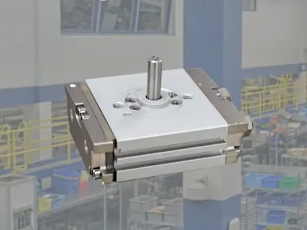
- Swinging or indexed rotation: quarter-turn valves, turntables, grippers that rotate. This is where “rotary actuator” in the motion-control sense (and the valve sense) is the honest answer.
- Extreme space constraints with low precision demand: where a packaged linear unit physically will not fit, and a motor-plus-lever does.
- Cost-sensitive builds where slop is acceptable: hobby rigs, simple dampers, anything where the load does not need repeatable positioning.
Notice what all four have in common: the application’s motion is rotation, or the precision requirement is low enough that the conversion risk does not matter. If neither is true, you are in the linear column.
Linear vs. Rotary Actuators
Linear Actuator

Rotary Actuator
The Trend That Changes the Math
The market is moving in one direction, and it matters for anyone choosing now. The global linear actuator market was valued at about USD 67.11 billion in 2025 (Mordor Intelligence, 2025). It is forecast to reach USD 91.36 billion by 2030, a CAGR of roughly 6.37%. Demand is growing across industrial automation, smart furniture, medical equipment, and agriculture, exactly the applications where linear output is the requirement.
Global linear actuator market: USD 67.11B (2025) to USD 91.36B (2030), ~6.37% CAGR (Mordor Intelligence, 2025).
The practical implication is not “always buy linear.” It is that supply chains are scaling up around packaged linear actuation: more models, more parameter combinations, more suppliers who can prove their numbers. If your equipment needs linear motion, the market is serving you better than it ever has. The selection problem has moved from “can I find one” to “how do I pick the right one,” which is the subject of the rest of this article.
| Your application | Default choice | Works because | Fails when |
|---|---|---|---|
| High-precision positioning (pick-and-place, lab equipment) | Integrated linear actuator | Deterministic screw motion, low backlash | Requires ball-screw-grade precision on a lead-screw budget |
| Heavy straight-line push/pull (gates, presses, lifting) | Integrated linear actuator (high-force) | Self-locking screw holds load without brake energy | Cycle time exceeds duty rating; vertical load on non-self-locking screw |
| Continuous rotation (fans, conveyors, spindles) | Rotary motor, no conversion | Rotary output is native | No linear conversion needed — a linear unit would be absurd here |
| Quarter-turn / indexed rotation (valves, turntables) | Rotary actuator (motion-control or valve type) | Native 90° output, high torque density | Requires linear output at the load |
| Quiet indoor / medical equipment | Linear actuator with non-metal gears | Low noise (under 50 dB class), self-locking, long life | High-speed or continuous-duty demands overheat it |
| Cost-sensitive, low-precision builds (hobby, simple dampers) | Motor + linkage/belt | Cheapest parts count | Slop, dead points, and wear become the failure mode |
Specs That Decide: Force, Speed, Stroke and Duty Cycle
Once you have settled on a linear actuator, the real selection begins, and this is where suppliers get separated. Four parameters decide most of it.
Start with force. Match the rated force to the real load, with headroom for friction and acceleration. Be aware that rated-force numbers are not all honest. Some catalog ratings are inflated relative to what the unit delivers at the end of its stroke or under continuous use. Ask what the number means: peak, at what speed, for how long. Treat “actual output exceeds the label” as the exception, not the rule.
Speed is not one number; it is a curve. Most DC linear actuators quote no-load speed (e.g., 20/30/40/50 mm/s tiers) and slow down as load rises. A forum regular put it plainly: “the more you load up a linear actuator, the slower its response.” If your cycle time depends on loaded speed, ask for the force-speed curve, not the headline number.
Stroke and mounting set the physical fit. Stroke ranges of 50–1,000 mm cover most equipment needs, but mounting is where custom work lives: bracket shape, hole patterns, clevis ends. A supplier with in-house machining can adjust these without redesigning the whole unit.
Duty cycle and lifespan govern the long game. Duty cycle (how many minutes of running per minute of rest) controls heating. Exceed it and a worm- or lead-screw unit overheats and accelerates wear. Lifespan is quoted in cycles. Typical catalog ratings hover around the 10,000-cycle mark, with higher-end units quoting 20,000–30,000 cycles. Always ask: what test produced that number? A lifespan claim without a test method behind it is a marketing sentence.
Run cycles you can prove: send us your duty profile and get an actuator spec’d around a test we can show you.
Send Your Duty ProfileControl and feedback turn the unit into a machine element. Limit switches tell the unit where to stop; position feedback (potentiometer or Hall sensor) tells the controller where the rod is at all times. If your application needs repeatable stops, these matter more than the motor itself. Pairing the actuator with a matched controller removes a whole class of integration problems: wiring, sync, and end-of-travel behavior.
Valve actuation is a special case. If you are selecting an actuator for a valve rather than a machine axis, the “linear vs rotary” question returns in a different form. Rising-stem valves (gate, globe) take linear actuators; quarter-turn valves (ball, butterfly) take rotary ones. Selection there runs on torque, ISO 5211 mounting interfaces, and fail-safe behavior. It is a different decision framework with the same underlying lesson: the valve’s motion requirement decides the actuator type, not the other way around.
The spec checklist
Force — What load, at what speed, for how long, at end of stroke?
Speed — Ask for the loaded force-speed curve, not no-load mm/s
Stroke & mounting — 50–1,000 mm covers most; brackets are where custom work lives
Duty cycle — Minutes on per minute off; over-rating heats the unit
Lifespan — What test produced the cycle number?
Control — Limit switches, feedback, matched controller
Environment — IP rating, temperature range, wash-down or explosion-proof needs
Where to Buy: What to Check Before Choosing a Supplier
The supplier is part of the mechanism. A good actuator from a supplier who cannot answer your questions becomes a bad actuator in your machine. When you evaluate vendors, check five things.
- Parameter transparency. Does the catalog give a complete parameter set (force, speed, stroke, duty cycle, IP rating) or only marketing highlights? The ones that hide the duty cycle usually have a reason.
- Test evidence. Can they show you the lifespan test, the aging test, the noise measurement? “Long life” is a claim; a test report is a fact. Ask specifically how the cycle rating was verified.
- Custom capability. Your mounting, stroke, voltage, or cable length will not match a catalog exactly. Can they machine brackets in-house, adjust speeds, split wiring? Suppliers without their own workshops outsource this and add weeks.
- Lead time and MOQ. For a prototype or a small first batch, does the supplier accept one unit? Do they quote standard lead times honestly (days, not months)?
- Certifications. CE, RoHS, ISO 9001 are baseline for most markets. For energy storage or hazardous areas, check for explosion-proof certification, a requirement that eliminates most actuator suppliers quickly.
This is not a ritual. Every item on this list is a question you will answer again when the unit is installed in your product. And the difference between a good supplier and a weak one shows up in whether the answers still hold six months later.
Why Linear Actuators Fail — and How to Avoid It
Linear actuators rarely fail dramatically. They degrade, and the degradation pattern tells you which part of the mechanism gave up:
The most common “actuator failures” are duty-cycle violations, not product defects. If the unit runs hotter than its rating, assume the mechanism is being asked for more than it was designed to give.
| Symptom | Likely cause | What to check first |
|---|---|---|
| Rod moves slower over time | Load exceeds the speed curve; worn screw/nut | Re-measure loaded speed; inspect screw for contamination and wear |
| Position drifts / repeatability lost | Backlash grew — worn nut, loose coupling | Check backlash at end of stroke; verify limit-switch repeatability |
| Unit runs hot | Duty cycle exceeded | Time the on/off cycle against the spec; check ambient temperature |
| Noise increased | Gear wear or lubrication loss | Listen where it is loudest; inspect gear material (plastic gears wear quieter than they fail) |
| Unit stops mid-travel | Overload protection or thermal protection tripped | Check load vs. rating; allow cool-down; verify supply voltage |
| Corrosion or moisture ingress | IP rating mismatch for environment | Match IP rating to the environment (wash-down, outdoor, storage) |
| Limit switch fails intermittently | Contamination or wiring issue | Verify wiring; check switch actuation force |
The pattern behind all of these: most failures are boundary violations, not random defects. Run the unit inside its force, duty, and environment boundaries and the mechanism wears slowly and predictably. Push it past the boundary and the failure comes from the part you were told about in the spec sheet but hoped you would not need. When you buy, keep the spec sheet, and check the unit against it in year one, not year three.
The Business View: What Your Choice Costs Over the Product’s Life
Purchase Price vs. After-Sales Cost
For an equipment maker, the actuator is a small line item on the BOM and a large line item on the service ledger. A unit that saves 20% at purchase but fails in the field costs you several times its price in installation labor, downtime, and customer confidence. This is why the mechanism decisions from earlier in this article (screw type, gear material, self-locking, test evidence) are business decisions, not engineering trivia. The 10,000-cycle unit and the 30,000-cycle unit may look identical in a photo. They are different assets once installed.
The 10,000-cycle unit and the 30,000-cycle unit may look identical in a photo. They are different assets once installed.
Verification Data Is Part of the Purchase
The suppliers who publish test methods are pricing verification into the product; the ones who publish adjectives are not. When you compare quotes, treat “tested, with data” as a component you are buying, not a favor you are asking for. In a market growing at over 6% a year, capacity is expanding fastest where buyers can verify what they order. Parameter transparency is becoming the default expectation, and suppliers who already operate that way are the ones whose numbers you can plan a product around.
None of this is theoretical for us. At Hoodland, we build electric actuators for equipment makers in energy storage, medical devices, and smart furniture. The questions in this article are the ones our customers ask before they order: which screw, which gear material, what test data. Our electric actuator line covers 20 N to 6,000 N at 6–24 V DC with strokes from 25 to 2,000 mm, and every unit ships with a 30,000-cycle rating verified by a two-hour aging test on that unit. See how we test every unit, because we believe the mechanism should have to prove itself, not just be described. If you are comparing suppliers for a motion project, ask them the questions from this article; the answers will tell you which column you are really in.
Spec the Actuator, Get the Test Data With It
Force, speed, stroke, duty: send the numbers and we’ll match a unit from our electric actuator line — 20 N to 6,000 N, 6–24 V DC, strokes 25–2,000 mm. Every unit ships with a 30,000-cycle rating verified by a two-hour aging test. No minimum order: a single unit is a legitimate build.
Discuss Your Actuator Spec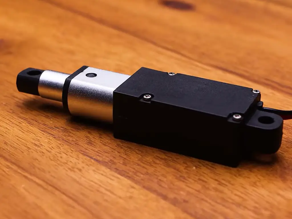
 English
  Chinese