
Stepper Motors vs Linear Actuators: What You’re Really Comparing
Ask most people the difference between a stepper motor and a linear actuator and you’ll get a clean-sounding answer: a stepper motor rotates, an actuator pushes in a straight line. That’s true, and completely unhelpful. Almost nobody is actually choosing between a spinning thing and a pushing thing. If you need linear motion, both options can give it to you. What you’re really choosing between is who assembles the rotary-to-linear conversion: you, or the manufacturer.
Before we go further, one quick clarification, because “linear actuator” is a crowded family. Linear actuators can be electric, pneumatic, or hydraulic. This article is only about electric linear actuators — the DC-motor-driven units with a gearbox and a lead screw inside a housing (in industrial catalogs, “electric actuator” can also mean a valve actuator; that’s a different product, and not what we’re covering here).
Also worth clearing up immediately, since it comes up in every search: do linear actuators use stepper motors? Yes — there’s a whole product category built around exactly that (stepper-motor linear actuators, or SMLAs), where a stepper motor and a precision screw are integrated into one unit. So “stepper motor” and “linear actuator” are not two exclusive choices like gasoline and diesel. They’re two ingredients, and the real question is where the line between your work and the factory’s work gets drawn.
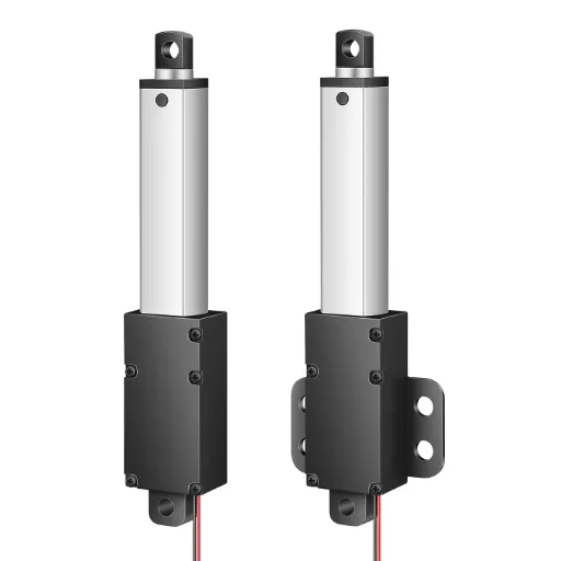
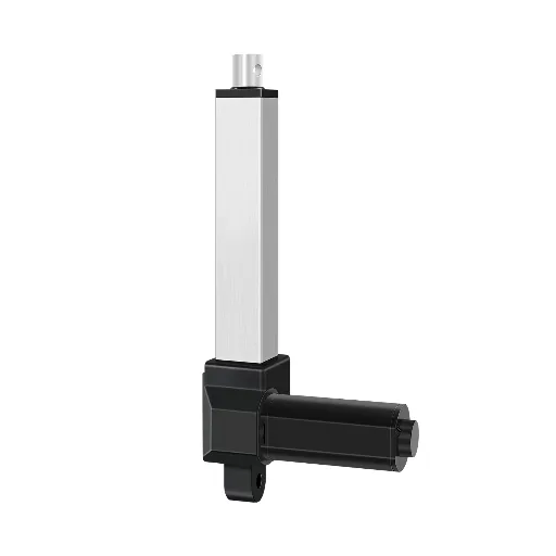
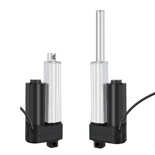
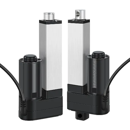
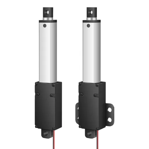
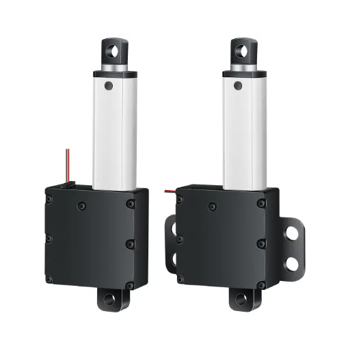
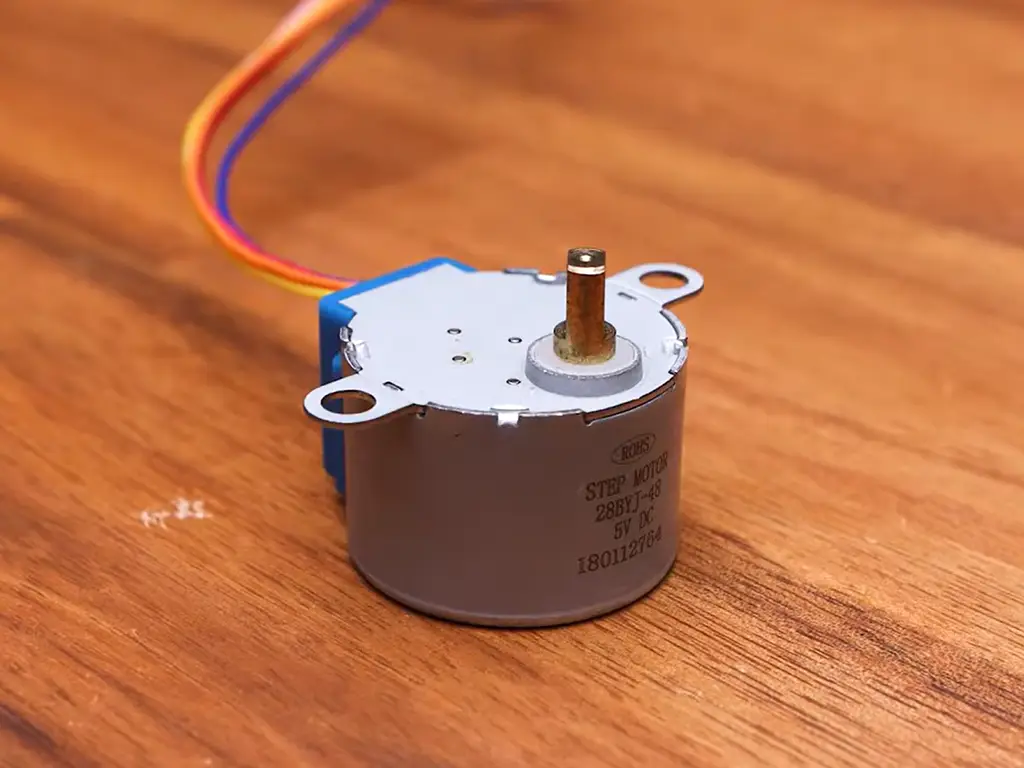
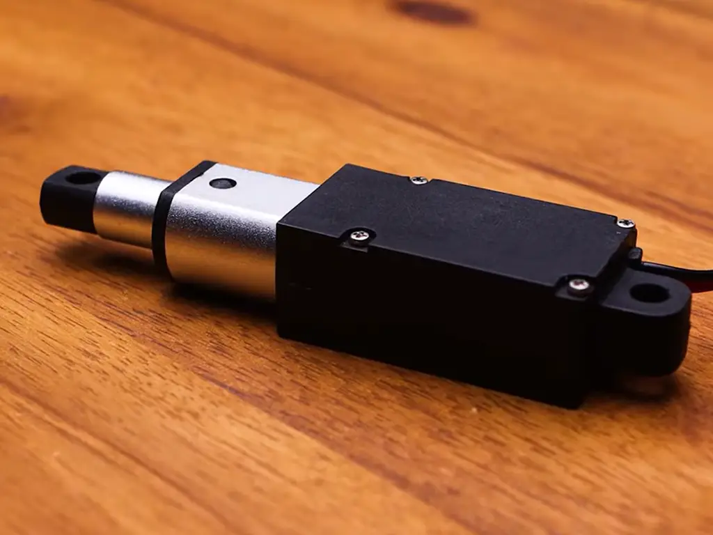
A stepper motor is a rotary motor that moves in fixed increments (typically 1.8° per step, or 200 steps per revolution). Feed it pulses and it rotates in lockstep with those pulses. That open-loop precision is why steppers dominate 3D printers and CNC machines. An electric linear actuator takes a DC gear motor, couples it to a trapezoidal lead screw, and packages the whole thing with limit switches and a housing so it extends and retracts a rod on command. The stepper is a component. The actuator is a product. Understanding that distinction is the entire article.
Stepper Motor vs. Linear Actuator
Stepper Motor
Linear Actuator
Four Ways to Turn Rotation into Linear Motion
If you want straight-line motion from an electric motor, there are four established ways to get it. They differ in one thing: where the rotary-to-linear conversion gets packaged.
Build It Yourself: Stepper + Lead Screw + Driver
This is the classic maker path — and the classic engineering path for prototypes. You buy a NEMA stepper motor, a lead screw and nut, a coupler, some pillow blocks to support the screw, limit switches, a stepper driver (A4988, DRV8825, or similar), and a microcontroller. Then you design and machine the mounting structure yourself.
The appeal is real: per-part prices look small, and you get full control over the motion profile. But the hidden work is where the cost lives. A lead screw needs proper bearing support — on the eng-tips engineering forum, one engineer documented a linear stepper whose unsupported screw end wobbled a full 1/16″ under load, ruining repeatability. Steppers also have a resonance zone (roughly 100–250 steps per second) where the motor can audibly vibrate and, in severe cases, lose steps entirely; you pass through it quickly or microstep through it, but you have to design for it. And nobody can tell you the lifespan of your assembly: a Pololu support engineer explicitly confirmed that stepper motors and drivers have no characterized lifetime data — “we do not have lifetime characterized.” For a hobby project that’s fine. For an industrial design, that’s a verification hole.
Stepper-Motor Linear Actuators (SMLA)
The stepper industry took the lead screw and pulled it inside the motor. In an SMLA, the rotor carries a threaded nut instead of a shaft, and the lead screw becomes the output. Rotary motion converts to linear motion directly inside the motor, which is why these units are so compact.
SMLAs come in three configurations: captive (the screw extends/retracts through the motor, with an anti-rotation spline), non-captive (the screw passes all the way through and moves independently), and external (a conventional rotary stepper driving a separate screw assembly). Their calling card is resolution. With a 1.8° stepper and a screw lead of 0.096″, each full step advances exactly 0.00048″. Microstepping (down to 1/64 step) makes movement visually smooth, but the accuracy ceiling stays at one full step. The trade-offs: you still need a stepper driver and a pulse source, output force is modest (tens of newtons to low hundreds), and the 25% duty-cycle rule applies. At rated current, “on” time should not exceed about one minute at a stretch. Haydon Kerk’s engineering literature is the best free reference for this product class, including their force-vs-velocity sizing curves and life-vs-load charts.
Integrated DC Linear Actuators
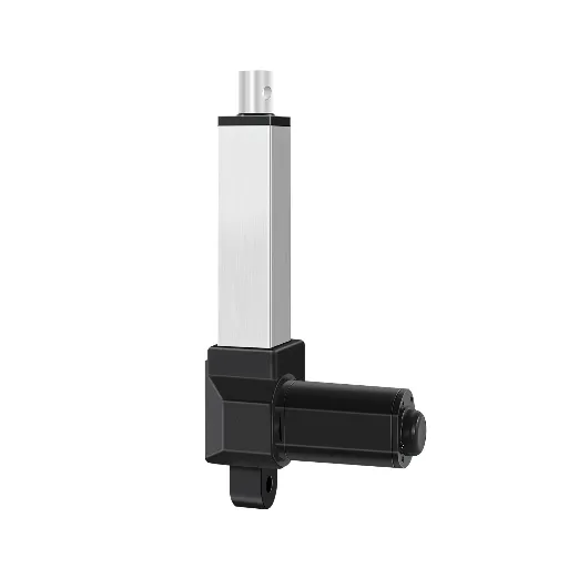
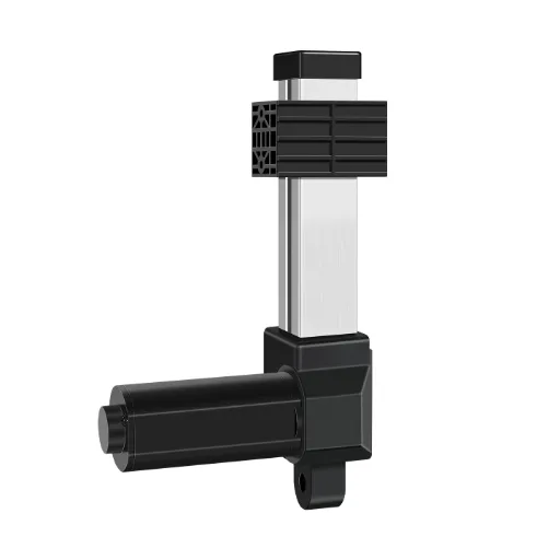
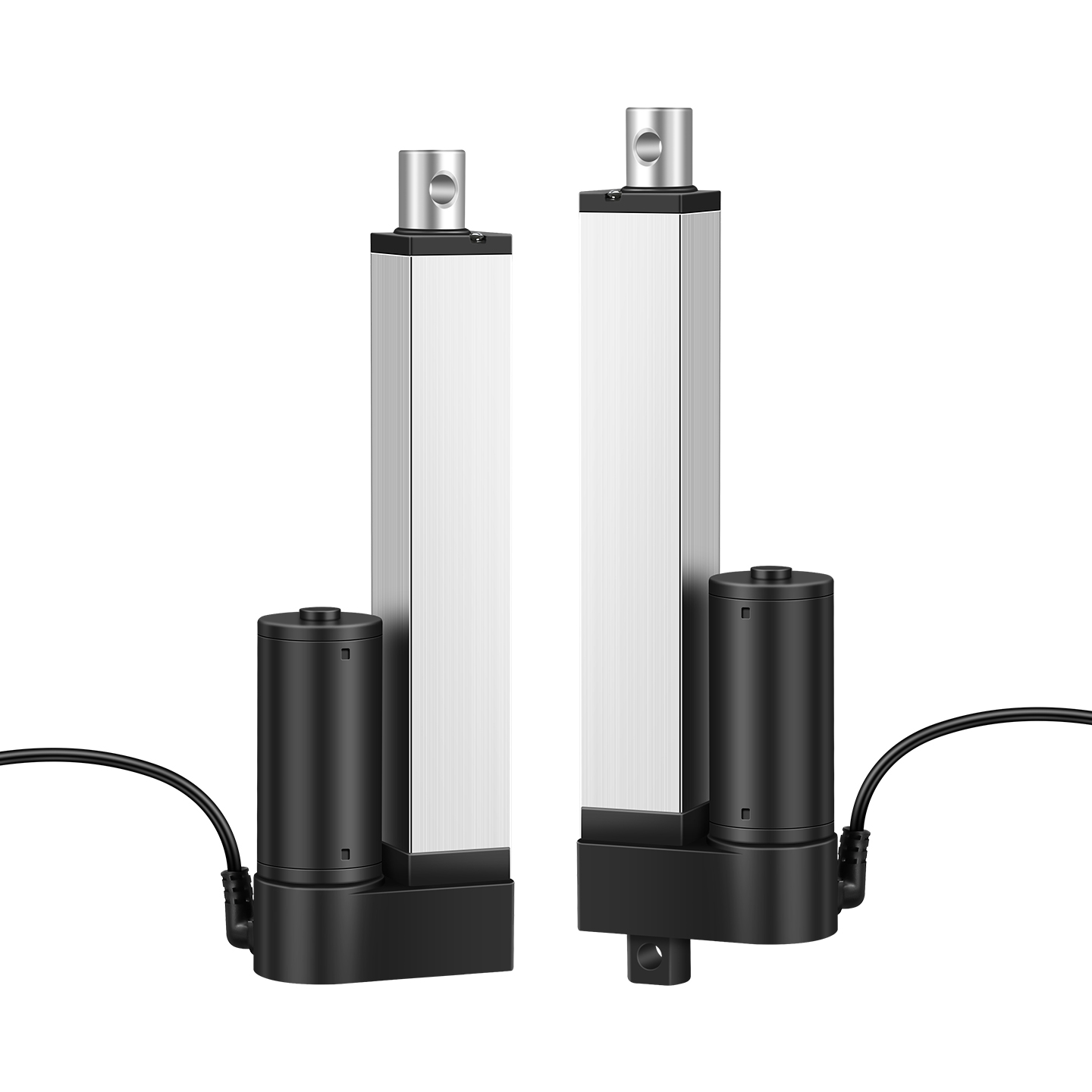
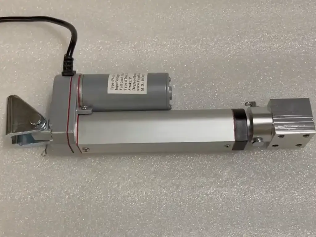
This is the product most people mean by “linear actuator”: a DC gear motor, a trapezoidal lead screw, limit switches, and a protective housing, assembled by the factory and delivered as one unit. You bolt it in, connect 12 or 24 V DC, and it extends and retracts.
The mechanical reasons these exist are the lead screw’s two gifts. First, a trapezoidal screw with a sufficiently shallow helix angle is self-locking: remove power and the load stays put. No brake, no holding current, no encoder loop. Second, the sliding screw-nut contact is far more tolerant of dust and debris than a ball screw’s recirculating balls, which degrade fast once contamination gets in. Inside the housing you typically find a polymer nut (Delrin/POM-class) for low friction and quiet running, plus limit switches or a position sensor for end-of-stroke control. Speeds are modest (tens of mm/s is the common range), and force spans from a few newtons to about a thousand for standard units.
Industrial-Grade Actuators
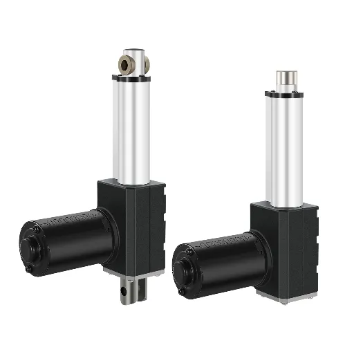
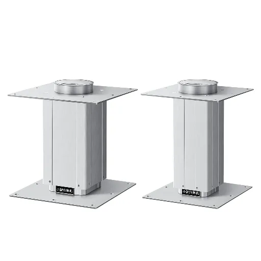
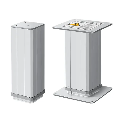
Take the integrated DC actuator and scale it for machines that run all day: higher thrust (into the multi-kilonewton range), continuous-duty ratings, IP44–IP65 protection against dust and water, overload and thermal protection, and — increasingly important in energy storage and process environments — explosion-proof variants (for example, Ex ib IIA T6 Gb certification, which few actuator manufacturers in the world offer). The duty cycle, not the headline force, separates industrial units from consumer ones. An actuator rated for 10% duty is a different product from one rated for continuous operation, even at the same force number.
One more industrial-layer difference matters in real purchasing: testing. Industrial actuators typically ship with per-unit test reports (run-in and aging tests, full functional checks), because the buyer’s machine reliability depends on unit-to-unit consistency, not just the datasheet.
| Approach | Packaging | Force Range | Duty Cycle | Control | You Build |
|---|---|---|---|---|---|
| Stepper + screw | You assemble every part | Tens of N typical | Intermittent | Open-loop step counting, driver needed | Shaft supports, coupling, limit switches, housing |
| Stepper-motor linear actuator | Screw integrated into motor rotor | Tens to low hundreds of N | 25% max, 1-min bursts | Open-loop steps, driver needed | Mounting and driver wiring only |
| Integrated DC actuator | Factory-assembled motor + screw + limits | N to ~1,000 N | 10–25% typical | Limit switches or feedback | Bolt-on, connect power |
| Industrial-grade actuator | Sealed, tested, certified unit | Up to 6,000 N and beyond | Continuous options | Feedback, controllers, safety | Specification and validation only |
Which Approach Fits Your Application?
Every comparison in this article reduces to two numbers about your application: peak load (in newtons) and duty cycle (what percentage of a shift the actuator is actually moving). Everything else follows from those two.
- Load under ~50 N, intermittent duty, one-off or small batch: the DIY stepper route (or an SMLA if you want the screw engineered for you) is legitimate. This is the learning, prototyping, and multi-axis-precision zone.
- Load in the tens to low hundreds of newtons, you value not designing a drive train: an integrated DC actuator is the answer — this is the sweet spot for furniture mechanisms, medical tables, vending, small automation.
- Load over a few hundred newtons, continuous duty, outdoor or dusty environments, or a product that must behave identically across thousands of units: you’re in industrial-grade territory, and that’s where the “buy, don’t build” argument stops being a preference and becomes an engineering decision.
| Your Situation | Choose This | Why |
|---|---|---|
| Prototyping, learning, or <50 N precision positioning | Stepper + screw, or SMLA | Full control, lowest per-part cost, open-loop precision |
| 50–500 N push/pull, intermittent, indoor | Integrated DC actuator | Self-locking, built-in limits, plug-and-play |
| >500 N, continuous duty, dust/outdoor/safety | Industrial-grade actuator | Sealed, tested, duty-rated, certified |
| Multi-axis robot or CNC-stage positioning | Stepper or servo + ball screw | Speed and closed-loop precision beat screw actuators here |
The trend data points the same direction. The global linear actuators market was valued at USD 67.11 billion in 2025 and is forecast to reach USD 91.36 billion by 2030, a 6.37% CAGR, with electric actuators taking 52.54% of the market in 2024 and growing faster than the category (8.56% CAGR) as manufacturers shift away from hydraulic and pneumatic systems (Mordor Intelligence, 2025). The narrower electric linear actuator segment is projected to grow from USD 25.4 billion in 2026 at a 5.5% CAGR through 2036, with DC-driven units the fastest-growing sub-segment (Future Market Insights, 2026). What that means at your level: the ecosystem of integrated electric actuators — including industrial-grade units with certifications and test data — is getting deeper every year, while the price premium over “build it yourself” keeps shrinking. If your machine is meant to ship in volume, the balance has shifted.
One honest boundary before moving on: none of this is a license to look down on the DIY route. For learning, for rapid experimentation, and for machines where precision positioning at low load is the whole job, a stepper plus screw remains the right tool. The argument here is specifically about production equipment that must run reliably for years — and for that job, the integrated product has the stronger case.
The market is moving — and it’s moving electric
Specifying an Actuator: Force, Duty Cycle, Protection, and Life
When you buy an integrated actuator, the datasheet becomes your contract. Work through these eight items in order.
The eight-item spec checklist
- Peak force, including dynamic and static loads — apply a minimum 2× safety margin over calculated load
- Speed in mm/s — remember force falls as speed rises
- Stroke and mounting distance — include mounting brackets and cable exit
- Duty cycle — 10%, 25%, or continuous changes the whole selection
- Environment — temperature range, IP rating, dust, moisture
- Life target — cycles × load rate × temperature
- Feedback and control — limit switches, potentiometer, hall sensor, encoder, controller protocol
- Supply voltage — 12 V or 24 V DC
The 2× force margin deserves emphasis. Haydon Kerk’s sizing literature, the standard reference for screw-driven actuators, is explicit: the first step in maximizing actuator life is choosing a motor with a safety factor of 2 or more, because life falls exponentially as operating load approaches rated load. An actuator run at 50% of rated force will outlast one run at 90% by a wide margin. Under-specify, and you are buying a warranty claim.
Lead Screws vs Ball Screws
Inside the actuator, the screw choice determines the personality of the unit. Trapezoidal (acme) lead screws are self-locking, hold position with power off, tolerate dust and contamination (sliding contact, no recirculating balls to clog), and are inexpensive — the right choice for the vast majority of push/pull actuator applications. Ball screws offer higher efficiency (less of your motor’s torque lost to friction), which enables higher speeds, but they’re back-drivable (no natural holding), need protection from contamination, and cost more. Roller screws — the high-load, high-life option — are the rare spec; mention them once so you know they exist when force requirements climb into tens of kilonewtons. For a typical actuator application, trapezoidal is the default; you move to ball screws when speed or precision demands it.
Two Numbers Decide Everything
Peak load and duty cycle. Send them to our engineers and get back a matched unit — motor, gearbox, screw, and feedback — sized from your real operating point, not a catalog guess.
Send My Load & Duty NumbersDC, Stepper, or Servo as the Prime Mover
The motor inside also has three personalities. DC gear motors are simple, cheap, and strong relative to their size — their weakness is that position control needs external feedback (limit switches or sensors), and they don’t hold position on their own. Steppers give open-loop position control with no encoder, no brushes to wear, but their torque is modest and falls off sharply at speed (community testing consistently cites ~500 rpm as a practical ceiling for NEMA-class steppers). Servo motors deliver the best dynamic performance and closed-loop accuracy, at the price of a driver, encoder, and tuning. The practical mapping: push/pull machines with high duty cycles take DC gear motors plus feedback; precision positioning takes steppers (or SMLAs); high-speed closed-loop motion takes servos.
Feedback and Control: Open-Loop, Limit Switches, Sensors
“Control” is where projects go wrong — usually by assuming the motor can do the positioning. A stepper counts its own steps, but a stall, resonance, or a missed pulse means the count lies. A DC motor without feedback doesn’t know where its shaft is at all. The robust pattern for actuators: mechanical self-locking (trapezoidal screw) + limit switches at the ends + a position sensor or controller when intermediate positions matter. That combination is why integrated actuators are so forgiving to design with — the factory has already solved the positioning problem for you, and you can add a potentiometer or hall feedback for analog position.
| Component | Options | Best For | Beware |
|---|---|---|---|
| Screw | Trapezoidal vs ball vs roller | Self-locking push/pull duty, dust tolerance, cost | Ball: back-drivable, contamination-sensitive, cost |
| Motor | DC gear vs stepper vs servo | High-duty push/pull, cost simplicity | DC: no position memory; stepper: torque falls at speed; servo: cost and tuning |
| Feedback | Open-loop, limit switches, potentiometer/hall, encoder | End-point control, cost simplicity, analog position | Open-loop: lost steps are invisible; encoder: cost and wiring |
What to Check Before You Buy from Any Actuator Supplier
Once your specification is written, the next risk is the data on the datasheet itself. Actuator specifications are loosely governed, and the gap between label and reality is a known industry problem: advertised thrust is frequently higher than actual output. One common trick is rating force at zero speed with no safety margin, where the real continuous force is a fraction of the number printed.
The four verification columns
- Dynamic force curve — thrust across the speed range, not a single “max” number
- Duty-cycle and life-test report — cycles at what load, at what temperature
- Protection and certification documents — IP rating certificate, and for energy-storage or hazardous areas, the explosion-proof certificate itself (Ex ib IIA T6 Gb-class units are rare — most actuator suppliers don’t hold one)
- Per-unit test data — evidence of run-in/aging testing and final inspection on every unit, not just sample testing
Commercial terms matter almost as much as the technical ones. Does the supplier accept a one-unit order? No-MOQ suppliers are rare and signal a custom-first capability, because small orders with non-standard specs are precisely what most factories turn away. What is the stated lead time — and what is it for a modified unit (a different motor, a custom stroke)? Sample turnaround is a good test of responsiveness. And what’s the warranty structure — full-unit coverage, and how do they handle a shipping-damaged unit?
If a supplier can’t produce test data and certification documents, that’s not a negotiation point; it’s a disqualifier for production use. If they can, you’ve found a counterparty whose numbers you can design against.
Failure Modes, and How to Read Actuator Life Claims
Every linear motion approach has its own way of failing. The table below is the failure map for all four approaches — what you’ll see, what causes it, and what to check before it becomes a field failure.
| Failure Mode | Diagnostic Signal | Preventive Check | Preventive Action | Switch Approach When |
|---|---|---|---|---|
| Lost steps (stepper) | Position drifts without an error signal | Resonance zone ~100–250 steps/s; marginal torque | Run acceleration through resonance fast; microstep; derate force | You can’t avoid resonance at operating speed |
| Open-screw whip | Output wanders or vibrates under load | Free screw end deflects visibly (documented 1/16″ on a forum thread) | Support both screw ends; shorten unsupported length | Unsupported length can’t be reduced |
| Stall / torque shortfall | Unit stops under load, current spikes | Rated torque at rated voltage doesn’t cover the load | Apply 2× force margin at operating speed | Load approaches rated force at full speed |
| Duty-cycle overheating | Unit gets hot, smells, degrades | On-time exceeds rating (25% rule: ~1 min max bursts) | Match duty rating to real cycle; add cooling | Continuous operation exceeds rating |
| Contamination ingress | Noise, friction rise, premature wear | Dust/water in the screw nut or housing | Confirm IP rating against environment; trapezoidal over ball screw in dust | IP rating below environment exposure |
| Undersized life rating | Early failure at rated cycles | Life claimed “at rated load” but used at 90%+ load | Life falls exponentially near rated load — derate to 50% | Life target exceeds datasheet derated life |
Now, the number that confuses everyone: actuator lifespan. Search “linear actuator lifespan” and you’ll see claims ranging from ten thousand cycles to twenty million cycles. All of them can be true — because “cycles” means different things in different documents. The industry baseline for DC push/pull actuators is on the order of 10,000 cycles at rated load — that’s what most consumer and commercial units are designed and tested to. Premium industrial units publish 30,000+ cycles at normal use — roughly twice the industry average — which is only meaningful if you know the load and temperature at which the test ran. And the “20 million cycles” figures you see from precision SMLA manufacturers are a different product, run at a small fraction of rated load under controlled conditions — the number comes from their life-vs-load curves, where life rises exponentially as load falls.
The rule that protects you: never compare two life numbers without normalizing the load, the temperature, and the definition of one cycle (extend + retract = one cycle). Ask the supplier for the test conditions, not just the number. The same discipline applies to force ratings — and it’s the difference between a spec you can design against and a number that looks good in a brochure.
The same word, three different tests
Before you compare two life numbers, ask what load, what temperature, and what “one cycle” means.
The Business Case: Electric Actuation and Your Supply Chain
Step back from the mechanics, and this decision is a supply-chain decision. The market data you saw earlier — electric actuators taking an increasing share of a growing linear actuators market, and DC-driven units the fastest-growing slice — means the integrated actuator ecosystem is getting more capable and more competitive every year. More suppliers, more certified units, more standard options at every force tier.
For your purchasing structure, three consequences follow from the facts already on the table. First, the hidden costs of the DIY route (shaft supports, coupling, housing, driver electronics, and the engineering time to design them) are real line items — and the failure modes you’d be inheriting (resonance, unsupported-screw whip, uncharacterized life) are all field-return risks. Second, the integrated route converts those risks into a single auditable unit: one part number, one datasheet, one test report. Third — and this is the practical shift — the supplier-selection question becomes: who can produce per-unit test data and certifications, at what lead time, and with what customization floor? When you compare suppliers, compare the four verification columns, not the brochure force numbers.
What this shift changes in your supply chain
Put the hidden costs on the books
Shaft supports, coupling, housing, driver electronics — and the field-return risk they carry
Collapse the risk into one auditable unit
One part number, one datasheet, one test report
Rewrite the supplier question
Per-unit test data, certifications, lead time, customization floor
The honest version of the recommendation: if your machine moves loads over ~100 N, runs a real duty cycle, or ships in volume, budget for integrated industrial-grade actuators and spend your engineering time on the machine, not on the drive train. Reserve the stepper-plus-screw route for precision positioning under light load, where it genuinely has no equal.
That’s the approach we follow at Hoodland. We build our electric actuators around self-locking trapezoidal screws and POM gears, which is why our units run under 50 dB and hold position with power off — and at normal use conditions our actuators are rated at 30,000+ cycles, about twice the industry baseline, with actual thrust exceeding the label rating rather than the reverse. Every unit goes through a 2-hour aging test and full inspection before it ships, and you can review the per-unit test reports and our electric actuator range directly. Whether you build or buy is your call — but if you buy, that’s the standard we think the data should be held to.
Put Your Spec to a Real Test
Send your load, duty cycle, stroke, and environment. We’ll match a certified actuator with per-unit test reports behind it — and no minimum order, so even a single prototype unit is a legitimate build.
Request a Spec CheckReferences
- Haydon Kerk Motion Solutions. “Stepper Motor Linear Actuators 101.” Accessed 2026. haydonkerkpittman.com
- Mordor Intelligence. “Linear Actuators Market Analysis.” Updated July 2025. mordorintelligence.com
- Future Market Insights. “Electric Linear Actuator Market Forecast and Outlook 2026 to 2036.” February 2026. futuremarketinsights.com
- Actuonix Motion Devices. “How Lead Screws Work in Micro Linear Actuators.” 2026. actuonix.com
- eng-tips Forums. “Linear Stepper Motor Leadscrew Runout.” 2015. eng-tips.com
- Pololu Robotics & Electronics Forum. “DC Motor or Stepper Motor.” forum.pololu.com
- Reddit r/robotics. “Searching for a Very Small, Very Fast Linear Actuator.” 2023. reddit.com
 English
  Chinese