
Why Mounting Decides the Life of a Linear Actuator
Every linear actuator you buy has one capability written into its datasheet: it pushes or pulls along the centerline of its rod. That is the whole machine. The force rating, the speed rating, the stroke rating, all of them assume the rod stays on that centerline. Mounting is the part of the system that keeps that assumption true.
Most applications do not move in a straight line. A hatch swings on an arc, a TV lift rises vertically, a solar panel tilts through an angle, a sofa back rotates around a hinge. As the actuator extends, the two mounting points move relative to each other. If the brackets at either end cannot rotate to follow that motion, the rod gets bent sideways, and the actuator starts working against itself. Binding, noise, heat, worn seals, a bent rod, a dead unit months before its rated life.
This article covers the mounting options that prevent that. You will learn how the common options differ, which one your mechanism actually needs, and how to verify a mount will hold up. You will also see when to stop searching catalogs and start specifying a custom interface. If you came here for valve actuator flanges or linear rail mounting kits, this is not that article. It covers rod-type electric actuators and lifting columns only. Everything else in this guide follows one question: how does your mechanism move, and what does that demand from the mount?
Linear Actuator Mounting Options, Grouped by How the Mechanism Moves
Vendor catalogs list mounting options by part name: clevis brackets, T-brackets, H-brackets, trunnion mounts, shaft-end brackets, body clamps, universal plates, kits. Three different suppliers give you three different lists, and each one insists its list is complete. That is because part names are not the organizing principle. The organizing principle is kinematics: how many degrees of freedom the mount allows, and where it touches the actuator. Grouped that way, every mounting option falls into four families, and every mechanism you will ever mount an actuator on belongs to one of them.
Rigid Fixed Mounts: Zero Degrees of Freedom
A fixed mount bolts the actuator body and the rod end to the structure with no pivoting at either end. The actuator becomes a rigid structural member, and every load must stay exactly on the rod’s axis.
Fixed mounting is correct only when the motion is straight-line push or pull, and the load is already constrained by something else. A guided slide, a fixture, a bellows, a button, or a mechanism riding on rails all qualify. The structure, rails, or hinges carry the load; the actuator only provides the force. The moment the load path bends, fixed mounts convert that bend into side load on the rod, which is the fastest way to destroy an actuator.
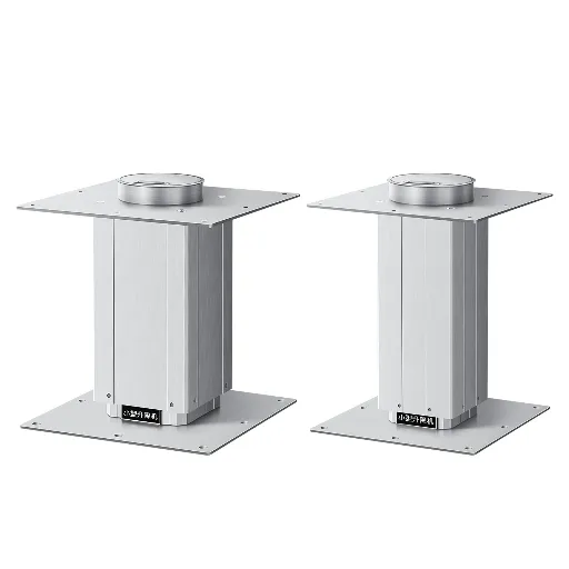
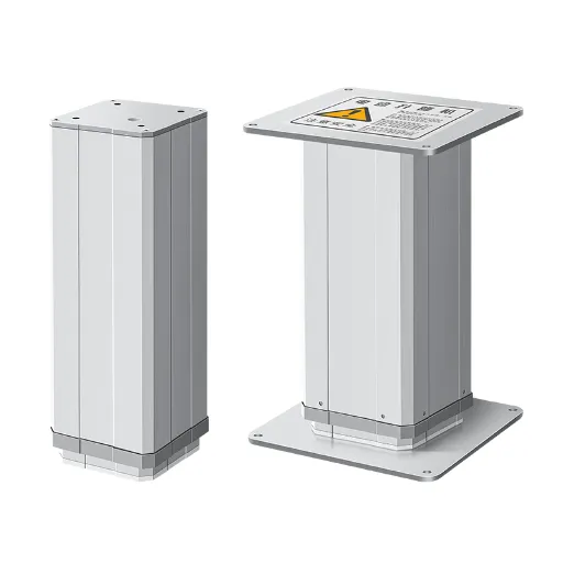
The classic correct use is a vertical lift with a fixed base plus a pivot at the moving end: TV lifts, standing desks, and lifting columns all work this way. One rigid end for stability, one pivot for forgiveness.
Single-Axis Pivot Mounts: One Degree of Freedom
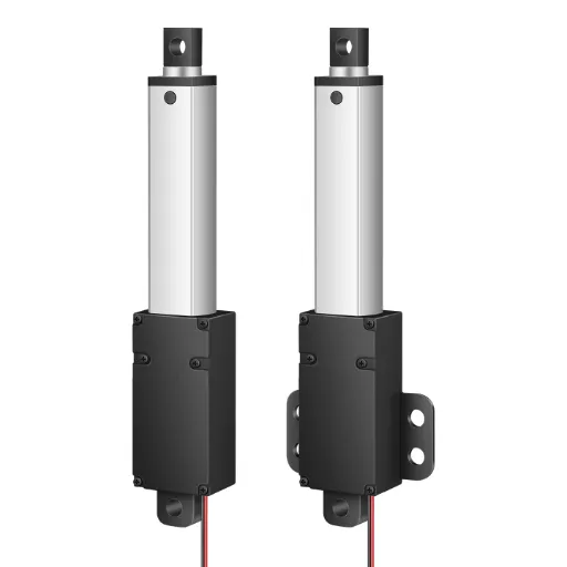
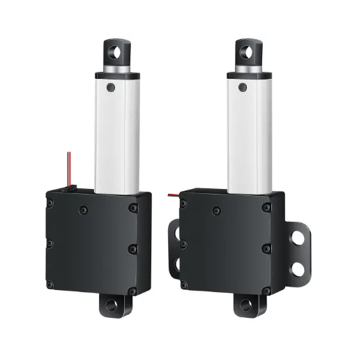
Pivot mounts allow the actuator to rotate around one pin axis. This is the most common family, and the clevis bracket is its most common member: a U-shaped bracket with a cross pin, one at each end of the actuator. Clevis brackets handle most swinging loads, because almost every door, hatch, lid, recliner, and adjustable panel moves through an arc.
The rule for pivots is simple: if the angle between the two mounting points changes during the stroke, you need a pivot at every end whose angle changes. Most swinging applications need pivots at both ends.
T-brackets are the second member of this family. They mount into a slot machined through the actuator end cap, which puts the pivot on the actuator centerline instead of offset to one side. Centerline mounting matters when alignment precision is critical, because an offset pivot introduces a moment arm the rod must fight.
Trunnion mounts are the third. A trunnion is a pivot block attached to the outside of the actuator tube, usually with two pins on opposite sides. It is the right choice when the actuator body itself needs to move with the mechanism rather than staying pinned at the rear. Agricultural equipment doors and ATV attachments use trunnion mounts for exactly this reason: the body swings with the load, and nobody pins the rear end.
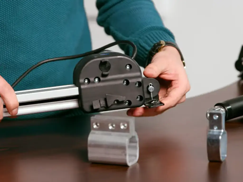
One member of this family is routinely misused. Body clamps wrap around the tube and tighten with bolts, which makes them look like a fixed mount, but quality ones still carry a clevis-style pivot. They exist to solve a positioning problem: clamping the body at an adjustable point along the tube when space or geometry rules out end mounting. A body clamp placed over the telescoping section of the tube is a guaranteed interference, and over-tightening can crush the housing.
Multi-Axis and Sliding Mounts: Compensation Without Binding
Some mechanisms cannot keep two pivot axes aligned, no matter how carefully you measure. This is where multi-axis and sliding options earn their keep.
Rod-end bearings, also called Heim joints or universal joints, use a ball insert that lets the rod end accept misalignment in more than one plane. A link terminated in two Heim joints can tolerate shafts that are not perfectly parallel, and window openers are the classic application. The ball joint accepts the misalignment angle instead of bending the rod.
Pin-and-slot mounts are the quiet alternative for a narrower problem. A slot in the bracket lets the pin slide as the mechanism rotates around its own axis, converting what would have been side force into sliding motion. Building automation engineers use this trick when a damper shaft rotates on its own centerline and a rigid pin would just apply side force.
The rule that unifies this family: when you cannot control the geometry, buy tolerance in the joint instead of strength in the rod.
The Commercial Part Names, Mapped to the Four Families
When you search for parts, you will see the names below. They are shopping terms, not engineering categories, so here is the mapping in one table.
| Part name | Kinematic family | Typical use | When it fails |
|---|---|---|---|
| Clevis bracket | Single-axis pivot | Doors, hatches, recliners, any swinging load | Both ends rigid on an arc; pin not secured |
| T-bracket | Single-axis pivot (centerline) | Precision alignment, slotted end caps | Misaligned pin; oversized clearance |
| Trunnion mount | Single-axis pivot on the tube | Body must move; agricultural, off-road | Pin spacing mismatched to tube diameter |
| Body clamp / shaft bracket | Pivot or rigid, position-adjustable | Retrofit, tight spaces, body support | Clamped over telescoping section; overtightened |
| Rod-end bearing (Heim) | Multi-axis | Non-parallel shafts, window openers | Operating angle beyond ball rating |
| Pin-and-slot bracket | Sliding compensation | Rotating shafts, building automation | Slot binds from debris or corrosion |
| Fixed base bracket | Rigid | Vertical lifts, desks, columns, guided slides | Load path off-axis; structure flexes |
| Universal plate / kit | Interface adapter | Bridging standard holes to custom geometry | Undersized fasteners; plate flex |
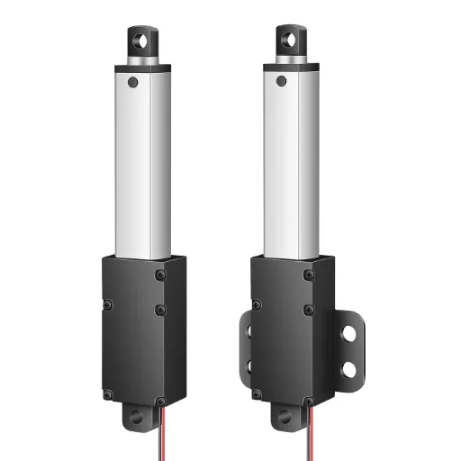
Pin diameters scale with the actuator. Micro actuators typically use M4 to M6 pins; industrial units use M10 and larger. The hole pattern and thread type vary between manufacturers, even within the same family. Never assume a bracket fits an actuator just because the name matches. The mounting hole specs on the actuator datasheet are the compatibility check, and they come before the bracket, not after.
Should You Use a Pivot Mount or a Fixed Mount?
You now have the full option set, so the next question is which one your mechanism needs. One question settles it, and it is a geometry question, not a preference question.
During the stroke, do the two mounting points change their relative position or angle? If yes, at least one end must pivot, and for most swinging mechanisms that means both ends. If no, the motion is pure straight-line, the load is guided by rails or structure, and fixed mounting is legitimate and often cheaper.
A pivot at one end only deserves a moment of attention, because it is the most common half-solution. A fixed base plus a pivoting top is correct for vertical lifting, where the base never moves and the top accommodates small misalignments. It is wrong for a door, where both ends swing through large angles and a single pivot just relocates the binding problem.
Two orientation questions come up constantly and have clean answers. Vertical mounting works, with two conditions: the load rating must account for gravity, and the mechanism must not be required to hold the rod aligned by itself. Angled mounting works at any angle, with the same two conditions plus one more. The brackets must let the actuator rotate freely through the full range, because the angle between mounting points changes even more aggressively in tilted installations.
One development is worth noting here, and it is a pattern observed in the field rather than a market statistic. Over the past several years, engineering forums have accumulated a steady stream of mounting questions that catalogs cannot answer. Engineers look for a bracket that does not exist in any catalog. Teams struggle with angled mount geometry. Integrators ask how much side load their actuator can actually survive. Standard brackets track standard mechanisms, and custom equipment has been outrunning standard ones. Mounting is quietly shifting from a selection problem to a customization problem, which is exactly what the next two sections prepare you for.
Still deciding between a pivot and a fixed mount? Send us your mechanism’s geometry and mounting points, and we’ll confirm the mounting approach before you drill.
Discuss your mounting interfaceSizing and Verifying Your Mount: Side Load, Brackets, and Alignment
This is where a mount stops being a part you bolt on and becomes a decision you verify. Three things need verification before the first hole is drilled. How much side load can the actuator survive? Are the bracket and fasteners rated for the real load? Are the alignment tolerances achievable?
Side Load: The 2–4% Problem
Side load is force applied sideways to the rod instead of along its axis. The numbers behind it are the most under-appreciated spec on any actuator. One widely referenced engineering-forum test of a typical 6-inch actuator rated for 250 N of continuous axial force found a side-load rating of only 5 to 10 N. That is roughly 2 to 4 percent of the axial capability.
SIDE LOAD vs AXIAL RATING
2–4%
250 N axial … only 5–10 N side
Misalignment is a spec violation, not a nuisance.
A mount that introduces 15 N of side load on a unit rated for 10 N has already exceeded the rating before the load is even attached. Side load comes from predictable sources, and each one is a checklist item. Misaligned brackets, unsupported heavy loads, a twisting frame, guide rails that are not parallel, loads mounted off-center, an actuator forced into its brackets, or a mechanism that swings through an unexpected arc.
The consequence chain is equally predictable. Binding comes first, then increased current draw, then heat, then accelerated wear on the seals and the screw, and finally a bent rod or a dead actuator. The sequence takes weeks or months to play out, which is why bad mounts get blamed on bad actuators.
Verifying the Bracket and Fasteners
A bracket rated for the actuator’s force is not automatically a bracket rated for your application. Three checks close the gap.
First, bracket load ratings are usually static ratings. A zinc-plated steel clevis bracket rated for a 159 kg static load tells you nothing about real conditions. Shock loads from a slamming hatch, vibration from a vehicle, and the 2 to 4 percent side load from an imperfect alignment all change the picture. With shock, vibration, or any side-load history, derate the bracket or step up in material. Steel beats aluminum for industrial duty. Stainless suits outdoor, marine, or food environments. Zinc-plated steel is the cost-effective middle ground.
Second, the fasteners must outrate the actuator, not match it. Undersized bolts are a standard failure point, because the actuator will happily exert its full rated force through whatever holds it, and the weakest link is the one that breaks. Use threadlocker on everything unless the assembly is designed for frequent disassembly; vibration works fasteners loose, and a loose bracket is a side-load generator.
Third, verify the bracket against the actuator’s mounting hole specs (diameter, spacing, thread type) before ordering. Brackets are not universal across brands, and the datasheet is the only authority.
Alignment: The No-Hammer Pin Test
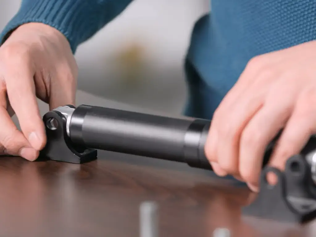
Alignment has one field test that every installer can run: the clevis pin should slide through both sides of the bracket and the actuator holes with minimal force. If you have to hammer the pin in, something is misaligned, and you have already found the future failure.
Misaligned mounting holes do not just make assembly hard. They put the rod under continuous side load and bend brackets long before the actuator reaches its rating. Manufacturers state this plainly in their own mounting documentation: misaligned holes introduce side load, bind the rod, and bend brackets well ahead of any component’s rated failure point.
The alignment standard, in checklist form: both brackets in the same plane; the pin free to rotate with no axial play. Check clearances at full extension and full retraction, because the angle between mounting points changes through the stroke. Finish with a low-load test before the real load is ever applied. If the unit binds, scrapes, or draws more current during that test, stop and fix the geometry. The test is cheap. The rework after a full-load failure is not.
The Mounting Decision Matrix
Here is the full decision tool, one row per mounting approach, with the boundary conditions that tell you when to switch.
| Mounting approach | Use it when | It fails when | Switch to this when |
|---|---|---|---|
| Rigid fixed, both ends | Straight push/pull, load guided by rails or fixtures | Mechanism swings; structure flexes | Pivot at one or both ends |
| Dual pivot (clevis/T) | Doors, hatches, any arc motion | Pivots not in the same plane; pins loose | Rod-end bearing if axes stay non-parallel |
| Fixed base + top pivot | Vertical lifts, desks, columns | Base structure not rigid | Dual pivot if the top swings through large angles |
| Trunnion on tube | Body must move with the mechanism | Tube clamped over telescoping section | Fixed base if the body should stay put |
| Rod-end bearing (Heim) | Non-parallel shafts, multi-plane motion | Operating angle exceeds ball rating | Custom bracket if angle is extreme |
| Pin-and-slot | Shaft rotates on its own axis | Slot binds with debris or corrosion | Rod-end bearing if angle grows |
| Guide rails + actuator | Heavy sliding loads | Rails not parallel; binding at joints | Dual pivot if the load swings instead of slides |
Read it the way a decision tool is meant to be read: start with your mechanism, not with the part. If your mechanism is not in any of these rows, that is not a failure of the table. It is the signal for the next section.
Where Custom Mounting Fits: OEM Mounting Interfaces
Standard brackets cover standard mechanisms, and the boundary of that coverage is real. Engineers have been posting versions of the same problem for years. “I need to mount the rod end to a shaft. I cannot find this bracket anywhere. I have tried every combination of ‘actuator mount’ I can think of.” The catalogs run out somewhere, and for OEM equipment, they run out earlier than for anything sold off a shelf.
When the mechanism does not match a standard bracket, the mounting interface stops being a hardware search and becomes a specification conversation. Three parameters define that conversation, and all three are negotiable at the manufacturer level. The first is mounting distance, the retracted dimension between the two mounting points. This is the parameter that decides whether the actuator fits your frame at all, and it is a per-design number, not a catalog number. The second is the end interface itself: the head and base fittings, whether pin holes, ball ends, or flanges, and where on the unit they sit. The third is the prototype loop, the ability to machine a custom bracket, bolt it to your frame, and test the geometry before committing to a production run.
The capability gap between suppliers shows up here, not in thrust ratings. A manufacturer that can adjust mounting distance, machine the end interfaces, and prototype in-house is having a different conversation. A supplier that only offers the next bracket in the catalog is not. When a sample of a custom mount turns around in days rather than weeks, the geometry risk in your project collapses. A single unit acceptable for the test is enough to start.
At Hoodland, this is how we treat every OEM mounting interface. Our mounting distance is set to your frame’s dimensions, not to a catalog page, and the head and base end fittings are machined to your interface. We prototype custom brackets in our own mold and CNC workshops, typically within 1 to 3 days for a sample, with no MOQ, a single unit accepted. Our custom mounting service page walks through the process, and our installation guide covers pre-installation checks plus downloadable manuals and wiring documentation. Getting the bracket geometry settled in the design phase is how side-load problems and the rework they cause get settled with it.
When you talk to any supplier about a custom mount, ask four questions. Treat the answers as the evaluation:
Four Questions Before You Order a Custom Mount
- Can you set the mounting distance to my frame’s dimensions?
- What end interfaces can you machine?
- Can you prototype the bracket before production?
- What is the minimum order quantity for a test unit?
The suppliers that answer all four with specifics are the ones where the mount will not become next quarter’s problem.
Mounting Mistakes That Fail Early, and How to Diagnose Them
Some mounting failures are slow and quiet, the current draw creeping up for months until the unit dies and everyone blames the motor. Others are fast and visible. Both are usually mounting failures wearing the costume of actuator failures.
A bent bracket is the fastest tell. In one recent field report, a drive motor bracket arrived bent after a few operating cycles, and the discussion was about how to straighten it. The answer is to not straighten it; a bent bracket is a statement that the geometry was wrong from the start, and straightening it re-issues the same side load. Misaligned mounting holes produce the same signature over a longer timescale, bending brackets well before any actuator reaches its rated failure point. And in the robotics world, a team testing an angled actuator mount found the geometry was the hard part, not the actuator. Designing a mount that keeps an angled unit free to move without binding is a design task in its own right.
Binding or scraping means bracket plane alignment is wrong. Noise means friction: check pivot pins, clamp torque, rod interference, in that order. Rising current draw means the rod is fighting something: check for side load before suspecting the motor. One-sided wear means the load path is off-axis: the bracket is doing the work the structure should be doing. Diagnose at low load or by hand, never at full load.
A loose mounting system has a distinct signature too: periodic clicks or knocks that disappear when the unit is unloaded. That is fastener fatigue, and it means threadlocker was skipped or the fastener grade was undersized. Retorque, upgrade, and threadlock, in that order.
Before first power-on, run the final checklist, every time:
Pre-Power Mounting Checklist
- Full-stroke clearance at both ends
- Pins slide in without hammering
- Both brackets in the same plane
- Fasteners rated above the actuator’s force
- Load supported by structure, not by the rod
- Wiring clear of pinch points
- Low-load test before full-load operation
Ten minutes of checklist saves the bracket and the actuator.
The Business Case: Treat the Mounting Interface as a Spec Item
For engineers and procurement leads at industrial equipment manufacturers, the previous sections have already made the business argument, so let it be explicit. The mounting interface is a specification item, and it deserves the same weight in the evaluation as force and speed. Three facts already established carry the case.
Side load cuts an actuator’s real capability to roughly 2 to 4 percent of its axial rating. That single number means an installation compromise is not a small inefficiency; it is a quantity-level reduction in what the machine can survive. Second, standard brackets track standard mechanisms, and custom equipment has outrun standard ones for years. That is why the mounting problem keeps showing up as a field failure and a forum post. Third, the mounting interface is one of the few parameters a supplier can customize without changing the actuator’s core ratings: the mounting distance, the end fittings, and the prototype loop.
For an OEM building equipment in energy storage, photovoltaics, swap stations, smart warehousing, or robotics, the arithmetic is direct. A supplier that sets the mounting distance to your frame and prototypes the bracket before production removes a whole class of rework from the project. No field shims. No re-drilled holes. No brackets replaced under warranty. The cost of that capability is one line in the evaluation spreadsheet. The cost of not having it is measured in the field, months later, in units that fail early and the diagnosis time that follows.
So the recommendation is deliberately narrow. When you shortlist suppliers for the next actuated product, add one evaluation column: mounting interface capability, covering mounting distance customization, end interface options, prototyping, and minimum quantity. Rate it with the same seriousness as thrust and speed. The suppliers that pass all four questions will tell you exactly what they can machine and when you can hold a sample in your hand. That specificity is the filter. The specification conversation is the cheapest design review your project will ever have, and it happens before any metal is cut, which is exactly where mounting problems should be settled.
Specify Your Mounting Interface Before You Drill
Custom mounting distance and end fittings, in-house prototype within 1–3 days, no minimum order. Send us your mechanism’s geometry and get a quote.
Request a custom mount quoteReferences
- r/engineering. “Actuator-like Product with High Side Load Tolerances?” 2019. reddit.com
- Firgelli Automations. “How to Mount a Linear Actuator with Clevis Brackets.” 2021. firgelliauto.com
- Firgelli Automations. “Common Mounting Brackets for Linear Actuators.” 2020. firgelliauto.com
- Firgelli Automations. “How to Rotate the Mounting Holes of Linear Actuators.” 2026. firgelliauto.com
- Progressive Automations. “Common Mounting Methods for Linear Actuators.” 2018. progressiveautomations.com
- Windy Nation. “Linear Actuator Mounting Brackets.” windynation.com

 English
  Chinese