
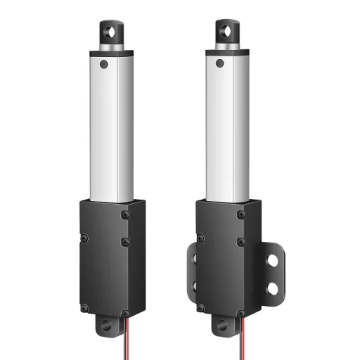
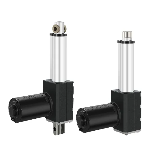
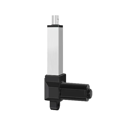
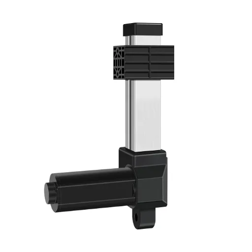
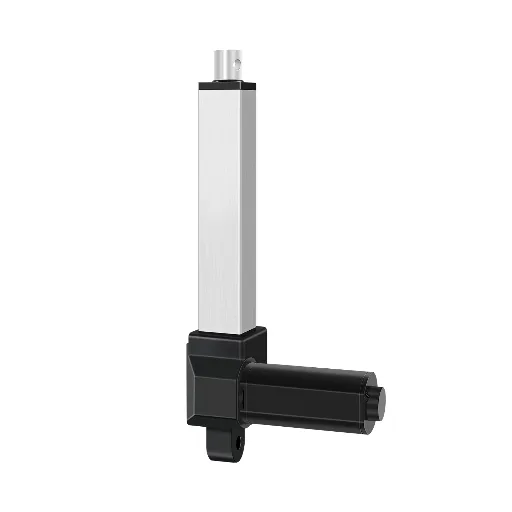
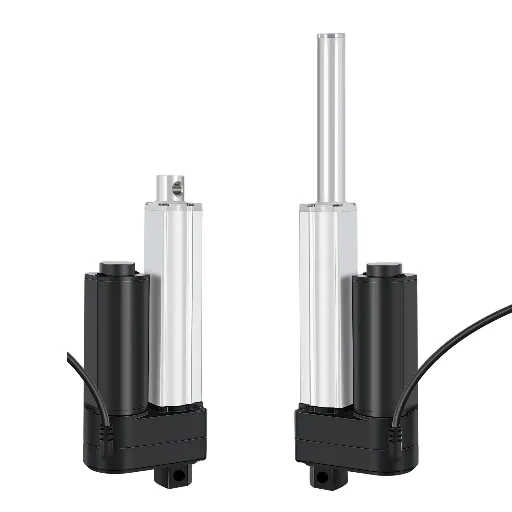
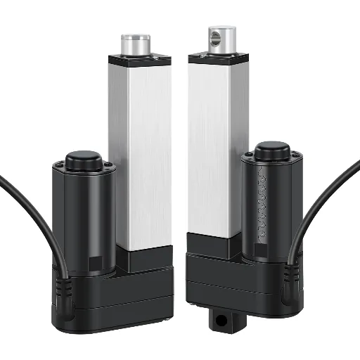
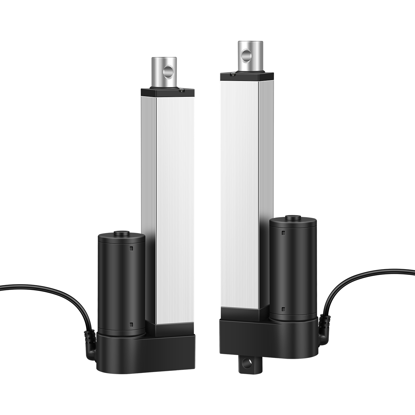
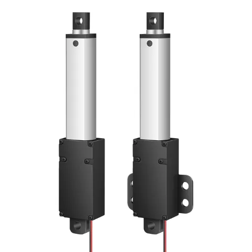
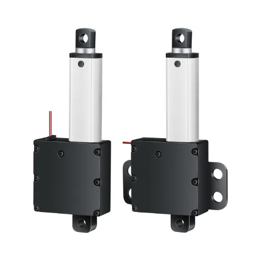
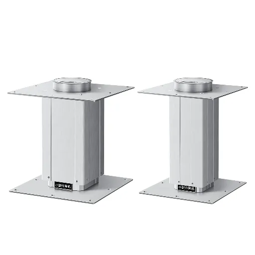
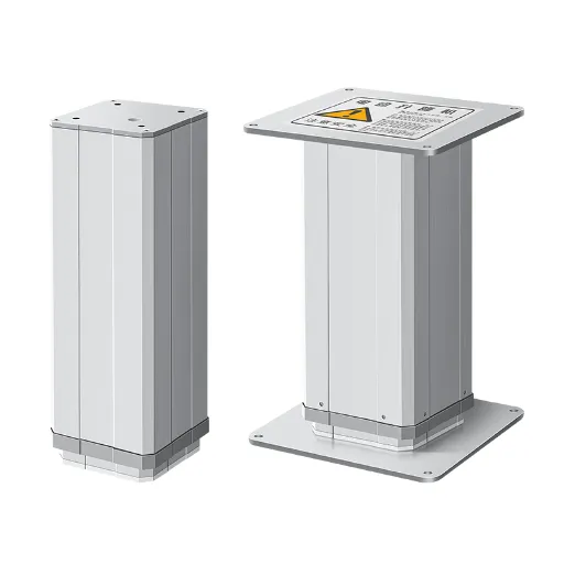
If you have ever stared at a linear actuator and wondered how two wires can make a motor stop at both ends of its stroke by itself, this guide is for you. Limit switch wiring is the part of an actuator installation that causes the most confusion, and the most damage when it is done wrong. This article walks through the full range of limit switch wiring: how built-in switches work, when you need external ones, how to wire them without trapping the actuator at an end of travel, and how to combine limit switches with relay control circuits.
How Built-In Limit Switches Work: Why Your 2-Wire Actuator Stops Itself
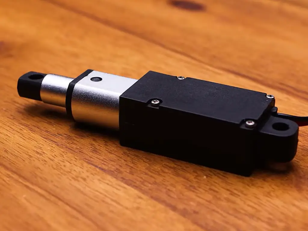
Most modern linear actuators ship with limit switches built in. It has become the industry default. One actuator-industry engineer put it bluntly in a farm-equipment forum thread: “Who sells an actuator without an internal limit switch? Seems odd” (AgTalk, 2014). If you are reading this because your actuator stopped by itself at full extension, you already own that default.
The mechanism is simpler than it looks. Inside the housing, a limit switch sits at each end of the stroke, wired in series with the motor inside the actuator. When the rod reaches full extension, a mechanical trigger opens the switch and breaks the motor circuit; current stops, the motor stops. Reverse the polarity and the motor runs the other way; the switch closes again the moment the rod leaves the limit position.
That is why a two-wire actuator with built-in limit switches needs only two wires: the stopping logic lives inside, in series with the motor. You do not wire the limit switches; they wire themselves into the circuit at the factory.
2-wire actuator with built-in limit switches
- 1Connect power supply + and − to the two actuator wires through your reversing switch
- 2Actuator extends; rod reaches full stroke
- 3Built-in limit switch opens inside the housing, breaking the motor circuit
- 4Actuator stops and holds
- 5Reverse polarity to retract; the switch closes as the rod leaves the limit
The cheap end of the market still sells 2-wire actuators without internal limits. These rely on an overload clutch: at the end of travel you hear a ratcheting click, and the motor keeps turning against the clutch. Hold the switch too long and the clutch wears — a recurring theme in the same forum, where a mower deck actuator “makes a loud clicking noise that I really don’t like but it seems to keep working.” The click is the clutch slipping, and it is not meant to be a lifestyle.
One more thing worth knowing before you wire anything: the 12V and 24V versions of this circuit are identical; voltage changes the power supply and the contact ratings, not the topology. Four-wire and five-wire actuators (with position feedback) move the limit logic into the controller; their wiring is a different story, covered below.
The Industry Default
Two wires. Both ends stop themselves.
Built-in limit switches are the industry standard — the stopping logic lives inside the actuator, in series with the motor.
Built-In vs. External Limit Switches: What Each Wiring Setup Can Do
The distinction that decides your wiring diagram is where the limit is enforced. Built-in switches are calibrated at the factory: they stop the actuator at full extension and full retraction, and they cannot be adjusted without opening the housing. External limit switches are mounted by you, anywhere along the travel, and wired into the control circuit.
| Built-in (internal) | External | Both (redundant) | |
|---|---|---|---|
| What it solves | End-of-stroke protection, out of the box | Stopping at a mid-stroke position you choose | Safety redundancy or synchronized stops |
| Wiring effort | None (factory-wired in series) | You wire switches into the control or motor circuit | External switches add to the built-in pair |
| Adjustability | Fixed at manufacture | Fully adjustable during install | External pair adjustable; internal pair stays |
| Failure boundary | If a cheap actuator skips them, end-of-travel damage | Exposed contacts need IP-rated switches in dusty/wet environments | Cost and complexity of two systems |
The practical rule: built-in limits cover the ends, external limits cover everything in between. A TV lift that must stop 20 cm before the ceiling does not need a different actuator; it needs external switches. An industrial door that must not crush anything even if the controller crashes needs both, as a hardware-level backstop that software cannot override.
Do You Need External Limit Switches? The NO vs. NC Decision
You need external limit switches when any of these is true: your stroke is too long for the space (restrict travel to a mid-stroke position), you need a safety limit independent of the controller, you run multiple actuators that must stop at identical positions, or you want a stop triggered by something other than the rod: a door edge, a light beam, a pressure mat. If full stroke works and nobody’s safety depends on it, the built-in switches are enough, and adding external wiring buys nothing but failure points.
The first wiring decision is switch type: Normally Open (NO) or Normally Closed (NC).
| Switch type | Resting state | When actuated | Fail behavior | Best use |
|---|---|---|---|---|
| NO (Normally Open) | Circuit open at rest | Closes, completing the circuit | If a wire breaks the circuit stays open and the actuator loses power silently | Signaling circuits (tell the controller “limit reached”) |
| NC (Normally Closed) | Circuit closed at rest | Opens, interrupting the circuit | If a wire breaks the circuit opens and the actuator stops — fail-safe | The standard choice for cutting motor power at a limit |
For cutting power at a limit, use NC. An NC switch that loses a wire fails closed… in the safe direction: the circuit opens and the actuator stops. An NO switch with a broken wire leaves the circuit open in a different way: the actuator simply never runs, which is also safe but invisible; and in the signaling role NO is correct. When in doubt for power interruption: NC.
If you design equipment, watch this trend: redundant limit protection is increasingly a standard expectation in industrial automation, not a premium extra. Equipment makers now ship actuators with built-in limits as the baseline and add external switches as the second layer, which is exactly the wiring task this article covers.
Do you need external limit switches?
- Yes if: travel must stop short of full stroke; safety requires a limit independent of software; multiple actuators must stop at identical positions; a stop must be triggered by an external object (edge, beam, mat)
- No if: full stroke is fine; the application is low-cycle; the switch would sit in a wet/dusty spot without an IP-rated housing
Wiring an External Limit Switch: The Diode Method and the 4-Wire Alternative
Why “stop at the end, still run backwards” is the hard part
Wire an NC switch in series with the motor and the actuator stops at the limit — but it will not run back. The switch that cut the motor also cuts the reverse current. This is not a wiring mistake; it is the geometry of the circuit. The AgTalk thread that gave this article its forum engineer spent a page of back-and-forth on exactly this problem, and the thread contains two working answers.
The diode method (2-wire)
The classic fix, used in commercial rate-control circuits for decades, is a diode in parallel with each limit switch. The diode is a one-way valve: it blocks current in one polarity and passes it in the other. When the NC switch opens at the limit, the diode carries the reverse polarity current so the motor can run back off the limit; the moment the rod clears the switch, the switch closes and takes over.
Wiring an external NC limit switch with diode
- 1Connect power + through the DPDT reversing switch to motor wire A
- 2Motor wire B connects through the NC limit switch to power −
- 3Solder a 1N4007 diode in parallel with the limit switch, cathode toward the positive side
- 4Repeat with a second switch+diode pair for the other end of travel
- 5Verify with a multimeter in continuity mode: NC contacts closed at rest, open when actuated
Two details matter. Diode orientation: install it with the cathode toward the positive side of the circuit. Reversed, the actuator locks at the limit and you will believe the switch is bad. And diode behavior: current through a diode drops a small voltage, so the actuator starts back off the limit slightly slower and speeds up once the switch re-closes. That brief hesitation is normal; it is the diode working.
A reversed diode locks the actuator at the limit permanently. Before you power up, verify continuity: NC contacts closed at rest, open when actuated — and check diode orientation against the wiring diagram.
A 1N4007 (1 A forward, 1,000 V reverse) handles most 12 V and 24 V installations (Firgelli Automations, 2026). Note that this circuit needs only two wires between the switch and the actuator, handy when you are retrofitting an existing machine.
The 4-wire alternative (no diodes)
The other school of thought runs four wires and skips the diodes entirely. Two NC switches (one for each direction) wire into the reversing switch so that the switch position that would drive the actuator into a limit is broken, while the opposite direction stays live. No diodes, no voltage drop, no orientation traps. The cost is four wires between the switch and the actuator instead of two, and a slightly more crowded reversing switch.
Both methods stop the actuator at the limit and let it run back. Pick by wiring budget: two wires plus two diodes, or four wires and nothing else. If this is a one-off retrofit on a machine you cannot easily re-run wiring on, take the diode method; if you are building a control panel from scratch, the 4-wire layout is the one maintenance people will thank you for.
Wiring Linear Actuators with Relays: Contact Ratings, Wire Gauge, and Circuit Layout
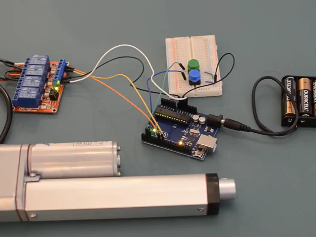
The relay question is the second most-searched wiring topic for linear actuators, and it is usually asked for the right reason: a relay lets a small signal (a switch, a timer, a PLC output) switch a large motor current, and two relays reverse the polarity.
Watch: Linear Actuator Relay and Limit Switch Wiring
This video demonstrates how relays and limit switches work together to control actuator travel.
The reversing relay circuit
One DPDT relay (or two 5-pin SPDT relays) swaps the + and − on the actuator leads: with both relays de-energized the motor is open; energize relay A and the actuator extends; energize relay B and it retracts. The coil side is your control signal; the contact side is the motor circuit: the two sides are electrically separate, which is the whole point of a relay.
Wiring a linear actuator with two 5-pin relays
- 1Common (30) of each relay: relay A to +12/24V, relay B to GND
- 2NO (87) of relay A and NC (87a) of relay B connect to actuator wire A
- 3NO (87) of relay B and NC (87a) of relay A connect to actuator wire B
- 4Coils: each relay coil driven by your control signal and common return
- 5Test: energize A only → extends; energize B only → retracts; both off → holds
Contact ratings and the melted-wire failure
The most common real failure in this circuit is not the actuator — it is the wiring around it. “12V Linear Actuators Keep Melting Wiring” is a recurring thread title on electronics forums (r/Motors, 2023). The root cause is usually the belief that an actuator “only draws the current it needs.” An electric motor draws what the load demands: stall current can be several times the rated running current, and a stuck mechanism can hold the actuator at stall for minutes. Two rules cover most cases: relay contacts rated at least 1.5× the actuator’s full-load current (a 10 A actuator wants 15 A contacts), and wire gauge to match: 18 AWG handles up to about 10 A on short runs; longer runs or higher currents step up to 16 AWG or heavier (Firgelli Automations, 2026). Add a properly sized fuse on the supply side; it is cheap insurance against the melted-wire thread becoming your own post.
Wiring numbers to keep
Combining relays with limit switches: power side vs. control side
Where the limit switch goes changes everything. Put the NC limit switch in the motor circuit (in series with the actuator lead) and it cuts power directly: the actuator cannot move past the limit under any failure, because the power path is physically broken. Put it in the control circuit (in series with the relay coils) and the relay drops out, but a welded contact or a stuck relay can still drive the actuator. For hardware-level protection, wire the limit in the motor circuit; for controller-supervised operation, the control side is where the PLC expects the signal.
| Control method | What it’s good for | Failure boundary | Switch to a better option when… |
|---|---|---|---|
| Direct reversing switch | Simple one-off, no automation | No interlock possible; current limited by switch contacts | You need automatic control |
| Single DPDT relay | Signal-controlled extend/retract, one actuator | No separate per-direction limits | You need independent limits per direction |
| Two 5-pin relays | Per-direction control, easily combined with limit switches | Two relays to size and wire | You need synchronized multi-actuator motion |
| Controller/PLC | Full automation, soft stops, position feedback | Costs more, needs programming | A simple toggle is all the job needs |
Solid-state relays (SSRs) work for high-frequency switching but generate heat and dislike stall current spikes; size them generously. And if your actuator has position feedback (five wires), do not fight it: feed the feedback to a controller and let it manage the limits, rather than bolting on hardware switches.
Troubleshooting Limit Switch Wiring: Why Your Actuator Stops Working (or Burns Up)
Every failure pattern in this article is someone’s forum post. The four classics, with the action that fixes them:
Limit switch wiring troubleshooting
- Actuator stops at the limit and will not run back: reversed diode, or diode missing on that end — check diode orientation, verify NC contacts close when the rod leaves the limit
- Wires or connectors getting hot: wire gauge too small for stall current, or actuator held at limit/stall for minutes — size wire to 1.5× load, add a fuse, check for a jammed mechanism
- Relay clicks but actuator does not move: contact side problem — welded or burned contacts, or the motor-side wiring is open; measure voltage at the actuator terminals
- Actuator stops mid-travel: limit switch triggered by something else — check switch mounting, cable dressing, and debris under the roller lever
Two checks catch most of these before power is applied: verify with a multimeter in continuity mode that NC contacts are closed at rest and open when actuated, and measure voltage at the motor terminals under load; if it sags far below the supply, you have a wire-gauge problem, not an actuator problem. On the bench, cycle the actuator into and out of each limit a few times before you mount it. That ten minutes is cheaper than the removal-and-ship cycle.
Designing Limit Control Into Your Equipment: What to Specify Before You Buy
Pull the threads from the earlier sections together and one pattern emerges: the limit-switch problems in this article are overwhelmingly retrofit problems. The diode workaround, the melted wires, the actuator that will not run back — all of them happen when a limit scheme is improvised at install time instead of specified at purchase time. The forum engineer who ended up opening his feed gate by hand because the wiring defeated him was not short on skill; he was short on a wiring diagram that matched his actuator.
For equipment that cycles thousands of times a year, the cost of that improvisation is real: downtime, replacement parts, and the engineering hours spent on what should have been a spec-line item. Three facts from earlier in this article support a straightforward purchasing rule. Built-in limit switches are the industry default: buying them as standard is not a premium, it is the baseline. External wiring, done properly, is the fragile part of the system: it adds contacts, diodes, and wire runs that can fail. And the retrofitter’s workaround exists to fix a mismatch that could have been avoided with the right stroke spec.
A checklist for the spec phase
Spec list for limit control
- Built-in limit switches: standard on every actuator model? Ask explicitly
- Stroke fits the application: custom strokes (25 mm–2,000 mm) beat external mid-stroke switches for production equipment
- Wiring documentation: manufacturer publishes wiring diagrams and an installation guide for your voltage
- Controller matching: actuator + controller sold as one compatible pair, with limit signals wired for it
- Testing evidence: units are load-tested before shipment, with a data report per unit
The same conversation that settles the stroke settles the wiring. Once the stroke is right, the limits are inside the actuator, the wiring diagram comes from the manufacturer instead of a forum thread, and the relay circuit you design is the relay circuit that ships.
Buying limit switches built in as standard is not a premium — it is the baseline.
If your build runs many cycles a day, spec the limits at purchase: Hoodland fits limit switches built in as standard, customizes stroke from 25 mm to 2,000 mm, and publishes wiring diagrams for all voltage options — so we can send you the exact diagram for your model before you buy. Start a custom project.
Get the Wiring Diagram That Matches Your Build
Limit switches built in as standard, custom strokes from 25 mm to 2,000 mm, and a wiring diagram for your voltage — before you order.
Discuss My ProjectReferences
- Firgelli Automations. “Adding External Limit Switches to Your Linear Actuator.” 2026. https://www.firgelliauto.com/blogs/tutorials/adding-external-limit-switches-to-your-linear-actuator
- AgTalk (New AG Talk forums). “Linear actuator limit switch wiring? How to?” 2014. https://talk.newagtalk.com/forums/thread-view.asp?tid=510945&DisplayType=flat&setCookie=1
- r/Motors (Reddit). “12V Linear Actuators Keep Melting Wiring..?” 2023. https://www.reddit.com/r/Motors/comments/1319wch/12v_linear_actuators_keep_melting_wiring/
- Hoodland. “IP60 Linear Actuator.” 2026. https://www.thehoodland.com/ip60-linear-actuator/
- Hoodland. “Linear Actuator Installation Manual / Wiring Diagrams & Schematics.” 2026. https://www.thehoodland.com/installation-guide/
- Hoodland. “Custom Solution.” 2026. https://www.thehoodland.com/custom-solution/
- Hoodland. Homepage. 2026. https://www.thehoodland.com/
 English
  Chinese