
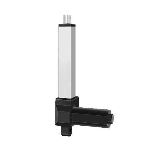
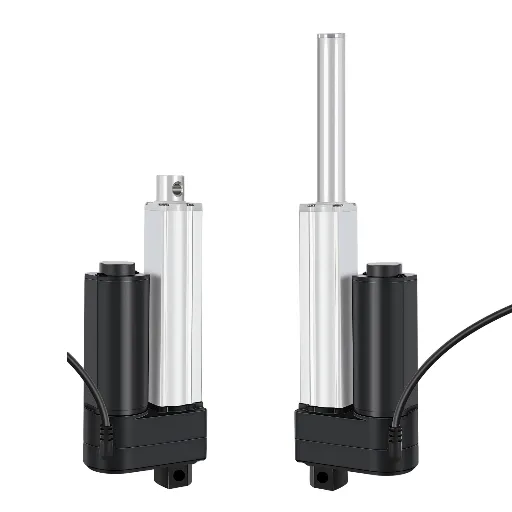
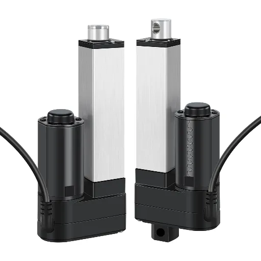
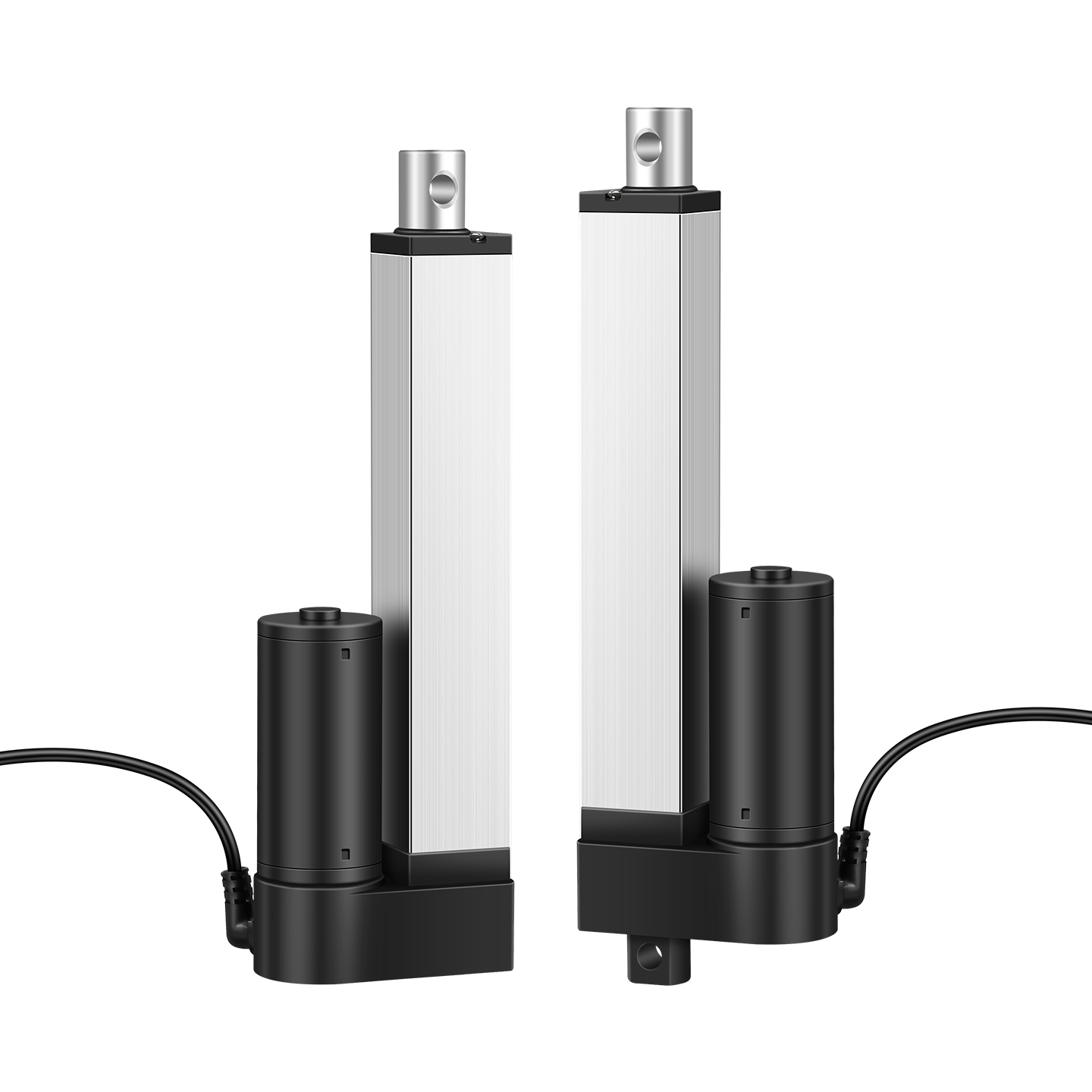
An AGV lift stage raises 200 kg of auto parts, holds for a scanner, then lowers and starts again, hundreds of times per shift. Every part of that cycle depends on one component class. Most sourcing debates start at the same place: which robot actuator type, driven by which power source, survives this duty?
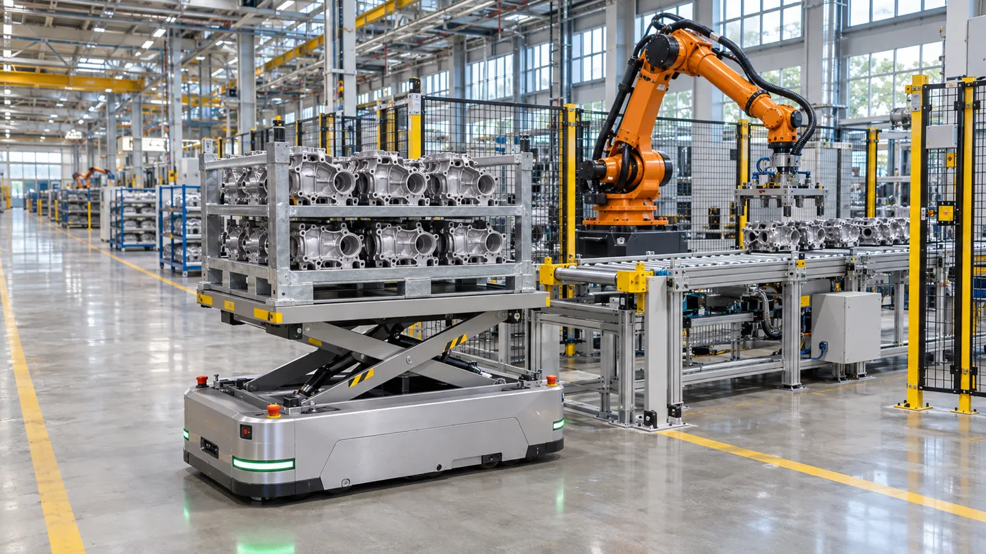
What a Robot Actuator Is: The Three Power Sources
An actuator is the component that converts stored energy into controlled motion. In a robot, that motion shows up as a joint rotating, a lift stage rising, a gripper closing, or a chassis rolling. Motors, cylinders, and gears are all parts of the answer, but the first sorting question is simpler: where does the energy come from?
Electric actuators use an electromagnetic motor, usually through a gearbox and a screw or gear stage, to produce motion. They are the default in modern robotics because electricity is easy to route, easy to control, and easy to measure. Position feedback and current monitoring come almost for free.
Hydraulic actuators push a piston with pressurized fluid from a pump station. Nothing else matches their power density, which is why excavation-class forces and heavy presses still use them. The cost is a full hydraulic circuit: pump, valves, hoses, filtration, and a maintenance schedule built around leaks.
Pneumatic actuators move a piston with compressed air. They are fast, forgiving, and cheap per cycle, and air failure modes tend to be safe. The weakness is control: air is compressible, so mid-stroke positioning is poor unless you add external measurement, which partly cancels the simplicity.
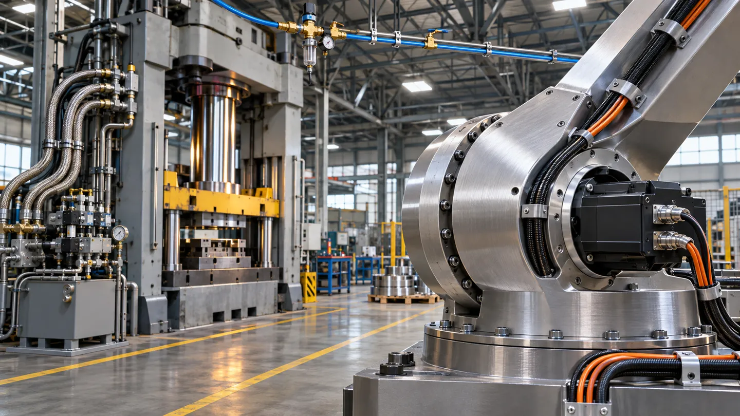
A few newer families exist outside these three. Piezoelectric stacks, shape-memory alloy wires, and soft elastomer actuators solve niche problems in micro-manipulation and compliant grippers. They matter for research and special applications, but they have not displaced the big three in production robotics.
The Three Power Sources at a Glance
| Dimension | Electric | Hydraulic | Pneumatic |
|---|---|---|---|
| Motion precision | High, supports closed-loop feedback | Moderate, affected by fluid compressibility and valve control | Low to moderate, poor mid-stroke positioning |
| System dependency | Power wiring only | Pump station, valves, hoses, filtration | Air compressor, FRL units, air lines |
| Maintenance focus | Lubrication and screw wear | Leak prevention and fluid condition | Seal wear and air quality |
| Typical robots | Most industrial arms, AMRs, cobots, grippers | Heavy machinery, high-force test rigs, large press robots | Pick-and-place endpoints, clamping fixtures, simple stops |
One sorting rule holds the rest of this guide together: the three power sources are only the first axis. Motion form, transmission, and feedback split each family further, and those splits decide most real selections.
Matching Actuator Types to Robot Tasks
Start from the task, not the catalog. A robot asks four different things of its actuators depending on where they sit, and each placement has its own logic.
Joints: Rotary Actuators With Precision Gears
A joint needs torque in a tight envelope, plus positioning that stays accurate after millions of reversals. That combination is why precision gear stages dominate here. Harmonic drives keep backlash to single-digit arc-minute levels and suit compact wrist and cobot joints. Planetary gears carry more torque per dollar and forgive dirtier environments. Cycloidal (RV) stages absorb shock loads in heavier industrial arms. One property matters more than any datasheet number: backdrivability. A joint that yields to external force is safer around people and easier to force-control, while a stiff, non-backdrivable joint holds position but resists the world. Large, slow joints are the exception that proves the rule: some heavy machinery drives them with a linear cylinder working through a linkage.
Lifting and Pushing: Linear Actuators
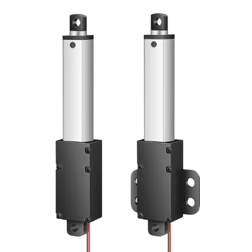
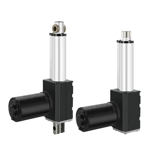
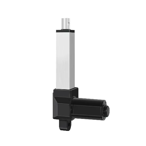
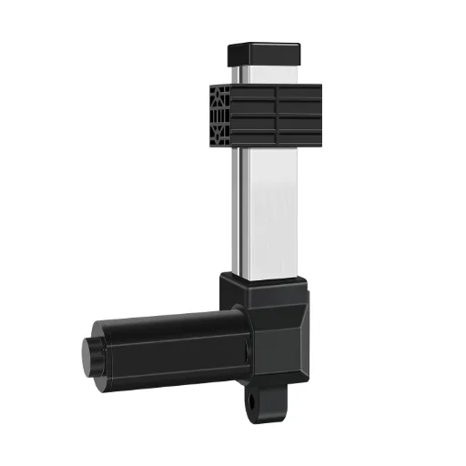
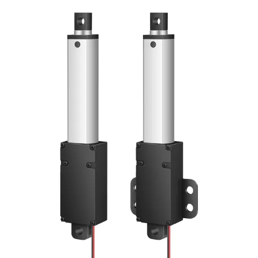
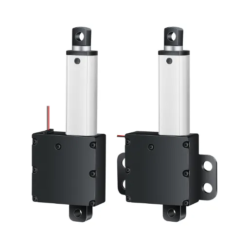
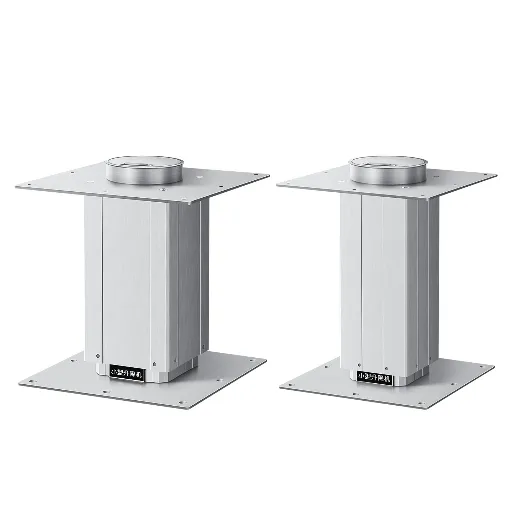
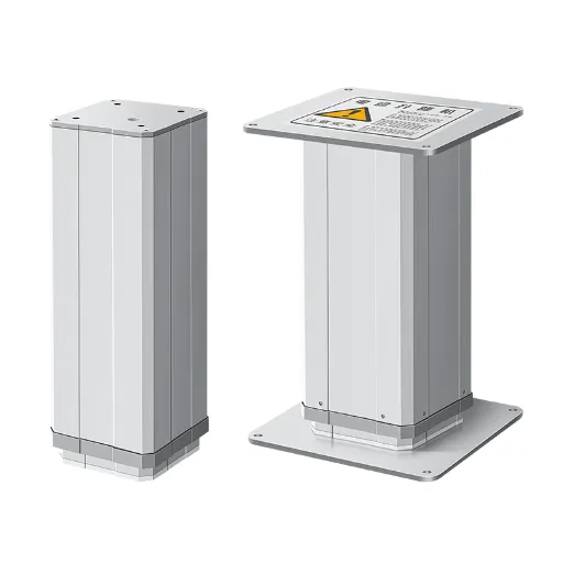
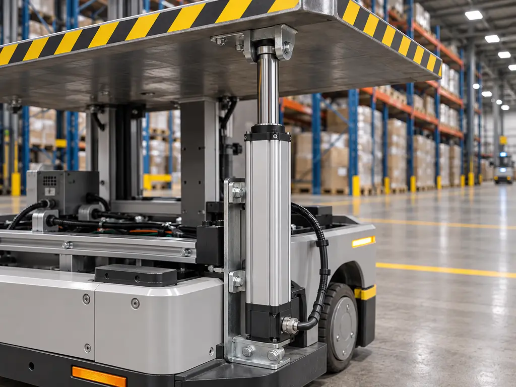
A lift stage or pusher works in a straight line. A linear actuator produces that motion directly, and saves the transmission you would otherwise build around a rotary motor. Thrust and stroke set the envelope. General industrial catalogs cover a wide span: micro stages around 20 to 150 N, mid-size rods from roughly 100 to 2,500 N, and heavy rods up to 6,000 N. Strokes run from tens of millimeters up to 1,000 mm, and longer on request. Speeds in the 5 to 100 mm/s band cover most handling cycles. The hidden requirement is coordination. Two lift stages raising one platform must track each other, and a storage shuttle that must return to the same height every time needs position memory. Both behaviors come from feedback, not from thrust, which is why the feedback section below carries so much weight.
Gripping: Compact Actuators and Electric Grippers
A gripper lives in the smallest space on the robot and works in short strokes. Micro linear actuators in the 20 to 150 N class, sometimes shorter than a finger, drive two-jaw grippers, tool changers, and small doors. What separates a good gripper axis from a toy is force control: sensing when jaws make contact and limiting squeeze so parts are held, not marked. Compressed air still wins some high-cycle pick-and-place endpoints on simplicity and price, but electric grippers take the job whenever part presentation varies and force needs to adapt.
Chassis and Drive: Wheels, Steering, and Integrated Units
Mobile platforms push a different priority: efficiency over force, because every watt comes from a battery. Wheel drive units pair motors with gearboxes sized for continuous running. Integrated units that combine motor, gearbox, and encoder in one housing have become the standard answer for AGV and AMR drive wheels. Steering columns and suspension adjusters lean on the same compact electric units as lifting stages. Two details separate mobile from fixed use. Brakes hold a loaded robot still on a slope with power off. Control integration matters more here, because mobile robots run through frameworks such as ros2_control rather than standalone PLC logic.
Task-to-Type Mapping
| Robot task | First-choice actuator | Parameters that decide it | Where selections go wrong |
|---|---|---|---|
| Joint rotation | Precision rotary unit: harmonic, planetary, or RV stage | Torque density, backlash level, backdrivability | Ignoring backdrivability, then fighting safety and force-control problems later |
| Lift and push | Electric linear actuator with position feedback | Thrust, stroke, speed, synchronization between paired units | Sizing thrust while ignoring duty cycle and side load |
| Gripping | Compact electric actuator or electric gripper | Short stroke, compact installation, contact force control | Over-sizing force and marking parts |
| Mobile drive | Integrated wheel-drive actuator with encoder and brake | Continuous efficiency, brake holding, control framework compatibility | Treating a fixed-arm motor choice as a chassis answer |
The mapping above is a starting filter, not a law. The same lift task can be solved with a linear rod, a rotary stage plus a linkage, or a scissor mechanism. Space, feedback needs, and budget decide which branch wins.
Why Electric Dominates Modern Robotics, and Where It Doesn’t
The scale behind this guide is worth stating once. The International Federation of Robotics reports a record five million industrial robots operating in factories in 2025, up 9 percent. More than 600,000 new units went in during that single year (International Federation of Robotics, 2026). Nearly every one of those machines runs on electric actuation, and the reasons are mechanical, not fashionable.
The Scale of the Shift
Source: IFR World Robotics 2026
Control is the first reason. Electric actuators take feedback loops in stride. An encoder or Hall sensor reports position, and a drive closes the loop. Synchronized lifting, position memory, and soft stops then become software settings. With valves you can copy this only by bolting measurement onto the cylinder, and that extra hardware eats the cost advantage air started with.
Integration is the second. A robot needs power wiring anyway, so electric actuators join the existing system without a pump room, air preparation units, or fluid disposal. Mobile platforms make this decisive: an AMR cannot drag a hydraulic power unit behind its battery pack.
Maintenance and total cost are the third reason. Hydraulic systems hold the force record, but they charge for it in leaks, filtration, and fluid management. Pneumatics are cheap to buy, and compressibility is what you pay with: poor mid-stroke control raises scrap and stretches setup time. Electric actuators cost more per newton up front, and less per year of closed-loop running.
The dominance has edges. Hydraulic still wins where force density is extreme, such as pressing, forming, and heavy mobile machinery. Pneumatic still wins where intrinsic safety is the requirement: spark-free operation in explosive atmospheres, simple and washdown-tolerant endpoints, and fail-safe retraction with air off. Even at the research frontier the question is open. Humanoid builders currently favor electric rotary and linear units, but the debate over muscle-like actuators versus conventional motor drives is very much unresolved.
Decision Rule
Choose electric when the task needs position control, coordination between axes, or data about its own motion.
Keep hydraulic or pneumatic for extreme force density and intrinsically safe tasks, where control finesse is not the point.
Before your next actuator RFQ, send us your real duty cycle and stroke, and get a sizing answer from an engineer instead of a catalog table.
Review my duty cycleSpec Sheet vs. Reality: Selecting an Electric Linear Actuator
With electric linear motion chosen, the selection work starts. It runs on three fronts at once: transmission, feedback, and operating boundaries. Spec sheets describe the first two honestly and the third hardly at all.
Transmission and Motor Type
The screw inside decides the personality of the actuator. Lead screws (trapezoidal screws) are economical and self-locking, which holds loads in place without power, at the price of lower efficiency and shorter life under continuous cycling. Ball screws recirculate balls to cut friction, so they run faster and cooler and last longer, but they are backdrivable and cost more. Planetary roller screws carry the heaviest loads and the longest lives in compact diameters, which is why aerospace and heavy industrial designs pay for them. Motor type is a shorter decision. Brushed motors minimize cost. Brushless motors trade an extra driver for longer life. Steppers hold position open-loop at low cost, and servos close the loop when accuracy matters. A duty-rated industrial rod with built-in limit switches covers a large share of handling tasks without custom engineering.
Feedback and Control
Feedback is what turns a moving rod into a measurable axis. With nothing but built-in limit switches, the actuator reaches its ends safely and stops there. A potentiometer reports analog position anywhere in the stroke, adequate for level control and simple monitoring. Hall sensors send digital pulses, which a controller counts into repeatable positions; this is the practical basis for memory positions and for paired actuators staying synchronized. Encoders raise resolution another step and support true closed-loop control with PLCs and motion controllers, including ros2_control-based mobile platforms. Match the feedback option to the behavior you actually need. Every step up costs money and wiring. Memory height and two-actuator sync are the most common real requirements, and Hall feedback is the workhorse answer for them.
Operating Boundaries Where Selections Fail
Three boundaries cause most field failures, and none of them appear as a warning on a typical spec sheet.
Duty cycle first. A rod actuator that lifts gracefully on a workbench can still overheat in production. Most rod-style units are rated for roughly 10 percent duty, or about 2 minutes of continuous operation. Convert your real cycle into a duty percentage before choosing. Static holding is different from dynamic cycling, and short tests hide the difference completely.
Duty Cycle Math
6 s stroke in a 60 s cycle
= 10% duty
Safe: the motor spends 90% of every cycle cooling off.
The same 6 s stroke in a 15 s cycle
= 40% duty
Over the rating: the motor cooks.
Side load second. Rod actuators are built for thrust along their axis, not for bending. Side loads arrive through skewed mounting, unsupported tooling, or guided loads that bind; they eat seals and screw threads and show up as early, repeated failures across a whole batch. Confirm mounting parallelism over the full stroke, and put an external guide on anything that weighs enough to resist being moved by hand.
Protection and environment third. Standard industrial rods sit around IP42 to IP54, which handles dust and splashes but not washdown. Somewhere between IP65 and IP67, sealing becomes a design commitment rather than a spec increment. Temperature windows around -20 to 65 °C cover most indoor plants, but not foundries or freezers. Confirm the actual rating and the test basis for your environment, including mounting orientation, because a vented housing rated IP54 pointing upward is not the same product pointing sideways.
Thrust claims deserve their own skepticism. Rated thrust is a generous number in this industry. Careful buyers measure actual force during acceptance. Demand the test basis for any thrust figure that matters to your application.
Pre-order checklist
- Duty cycle calculated from the real production cycle, not a bench test.
- Side-load path confirmed: mounting parallelism and external guides where needed.
- IP rating matched to the real environment, with mounting orientation checked.
- Temperature window confirmed against the worst corner of the plant.
- Feedback type chosen for the behavior you need: endpoints, memory position, sync, or closed loop.
- Acceptance test defined on measured thrust.
The checklist above assumes the choice is already made. The matrix below covers the earlier question, when a boundary pushes you away from the default answer entirely.
Boundary Matrix: When the Default Choice Stops Working
| Scenario | Default choice | Confirm before ordering | Switch when |
|---|---|---|---|
| AGV/AMR lift stage | Electric linear rod with Hall feedback and brake option | Duty cycle under paired synchronization; brake holding force | Stroke exceeds about 1 m or duty runs continuously: move to scissor or rotary-plus-linkage |
| Packaging pusher or diverter | Electric rod sized on real cycle duty | Cycle rate and product weight variance | Rates beyond electric duty limits: pneumatic endpoint wins on cost per cycle |
| Washdown food or pharma equipment | Sealed rod, IP65 and up, stainless options | Actual ingress test basis and orientation | Aggressive chemicals present: consider pneumatic with stainless body |
| Foundry or freezer cells | Rod rated for the extended temperature window | Real temperature extremes, not room-adjacent averages | Outside standard windows: hydraulic or custom thermal design |
| Explosive dust or gas zones | Pneumatic by default, or certified explosion-proof electric | Certification match to the zone definition | Certified electric units exist for the zone and feedback is mandatory |
The pattern across all five rows: the default answer holds until an operating boundary says otherwise. The boundary is always a measurement question, never a catalog question.
Field Failures: What Breaks Robot Actuators and Why
Failures in the field cluster into four patterns, and each has a diagnosis you can run without a lab.
A quiet bench test proves nothing about duty cycle. Motors that pass a short static check can still overheat within an hour of continuous cycling.
Overheating in production, after a clean commissioning test, is the classic first pattern. One robotics builder documented it directly: the motor held a load quietly for a short test, then overheated once the runs became sustained (r/robotics, 2026). The cause is almost always duty cycle read as a peak rather than an average, sometimes combined with a voltage supply running out of spec. Recalculate duty from the real production rhythm and verify supply voltage under load.
Early failures across an entire batch point to installation, not manufacturing. A student competition team traced repeated actuator failures to excess friction in their own mechanism: the actuators were fighting a side load their mounting never intended (Chief Delphi, 2026). Industry failure lists agree on the usual suspects: overloading, side loading, wrong voltage, water ingress, and exceeded duty (Actuonix, 2025). When every unit fails the same way at the same age, measure mounting parallelism before you blame the supplier.
Position drift and lost synchronization form the third pattern. A lift pair that used to stop level starts arriving tilted; a memory position stops being memorable. The feedback chain is the suspect: a Hall sensor out of alignment, a loose coupling, or wear in a screw chosen one duty class too low. Burned-out motors belong here too, usually traced to improper duty cycle, wrong voltage, or contamination working its way inside (Tavoron, 2025).
Water and contamination close the list. An ingress failure is rarely the seal’s fault alone. It is a mismatch between the IP rating, the real spray and dust exposure, and the mounting orientation the designer chose. Re-check the environment against the rating, then check the orientation.
These four patterns share something important: three of them were decided at the selection stage, before the actuator ever shipped. Failures teach the same lesson as the boundary matrix above, just with less paperwork.
Sourcing Checklist: What to Demand From an Actuator Supplier
Everything so far reduces to one purchasing claim. Boundaries decide field success, and boundaries are proven by evidence, not by catalog tables. That claim reorders how a robotics or automation equipment manufacturer should evaluate suppliers: read the parameter table fourth, and evaluate three things before it.
First, demand boundary evidence. Ask how the rated duty cycle was established and request the test basis, not just the percentage. Ask whether thrust figures are rated or measured, and what the actual-force tolerance looks like on receiving inspection. Confirm which IP rating applies in which mounting orientation, and the temperature ceiling in your worst plant corner. A supplier who answers these fluently has run the failures already; one who quotes the catalog back to you has not.
Second, demand quality process evidence. A burn-in followed by full inspection of every unit is a different commitment from sampling. It is also checkable: ask how long the aging test runs, and what parameters each unit is inspected against. Verify the certification set that your market requires, typically ISO 9001 for the factory, CE and RoHS for the products, and explosion-proof certification where zones demand it. If third-party inspection matters to your process, ask how the factory supports it, because material and test documentation is what the inspector will ask for.
Third, demand responsiveness. Prototype-to-production friction is a hidden schedule cost. Confirm whether customization carries a minimum order quantity, because design iterations almost always arrive in single digits. Ask for sample lead times in hours or days rather than weeks, and for a delivery commitment split between standard and custom configurations. Check the warranty term and what the after-sales response commitment actually says, in writing, for overseas customers. A design life quoted around 30,000 cycles is a useful scale reference for what serious industrial units claim, but always ask what test stands behind the number.
Supplier evaluation order
- Boundary evidence: duty-cycle test basis, measured vs. rated thrust, IP and temperature confirmation.
- Quality process: burn-in duration, per-unit inspection records, ISO 9001, CE, RoHS, zone certifications.
- Responsiveness: no-MOQ customization, sample lead time, standard vs. custom delivery split, written warranty and support terms.
- Only now: the spec sheet.
The selection stance follows from the whole guide. For lifting and pushing tasks, hold the line on electric linear actuators with position feedback, because pneumatic alternatives cannot close the loop that synchronization and memory positions require. For everything else, let the boundary matrix make the argument.
That third block in the checklist is where we built our own answer. Hoodland treats a single-unit custom order with the same process as a production run. There is no minimum order quantity. Our in-house mold and machining workshops build custom brackets and mounting parts, and prototype samples ship within 72 hours. Our standard line spans 20 N to 6,000 N of thrust, with strokes from 25 to 2,000 mm and speeds from 5 to 100 mm/s. Every unit ships after aging tests, backed by a one-year warranty. We keep controllers and feedback options in the same catalog, so the loop closes at one supplier. If you are building a shortlist, our custom electric actuator solutions page lists the full customization range.
Scope a custom linear actuator with Hoodland
Send thrust, stroke, speed, and duty cycle. You get a sizing recommendation, a no-MOQ custom path, and a 72-hour sample plan.
Start a custom actuator inquiryReferences
- International Federation of Robotics. “Five Million Robots now Operate in Factories Globally.” 2026. ifr.org/ifr-press-releases/news/five-million-robots-now-operate-in-factories-globally
- r/robotics. “Actuator Load Test for Fun.” 2026. reddit.com/r/robotics/comments/1ttng4b/actuator_load_test_for_fun
- Chief Delphi. “Actuonix Linear Actuator Failures.” 2026. chiefdelphi.com/t/actuonix-linear-actuator-failures/516106

 English
 Chinese