
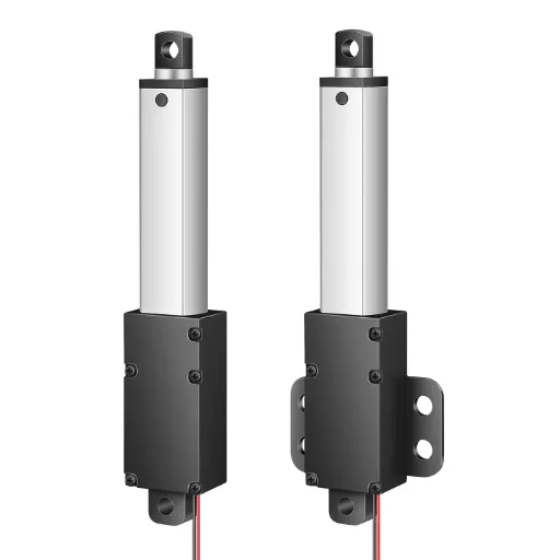
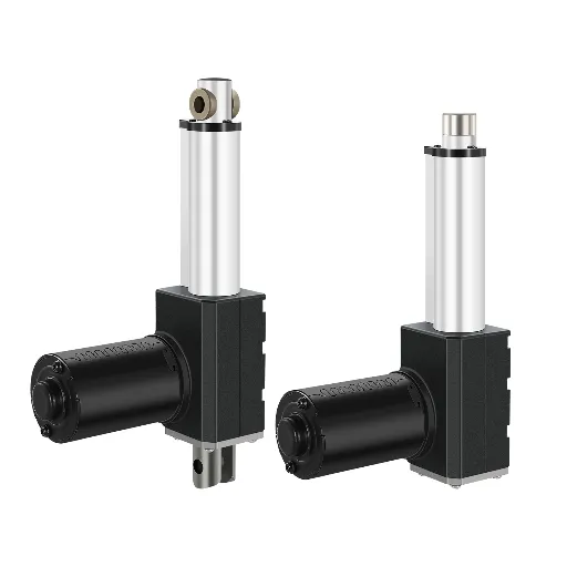
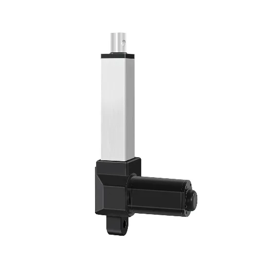
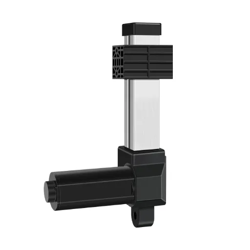
Search for “force controlled linear actuator” and you’ll find sensor makers pitching load cells, controller vendors selling closed-loop boards, and forum threads of half-answers. No one shows you the whole map. There are exactly four ways to implement force feedback on a linear actuator, from a few-dollar limit switch to a servo-grade closed loop, and most projects pick wrong because they never saw the map before buying. This guide lays out all four paths, where each one fails, and how to choose.
What “Force-Controlled” Actually Means
“Force control” is not a product category, it is a control strategy. A standard linear actuator is position-controlled: command a stroke position, it extends and stops. A force-controlled actuator is commanded to push with a given force, and hold it, even if the load is soft, moving, or creeping over time.
That change has a mechanical price. Position control needs a motor and limit switches. Force control needs three things working together: an actuator with the required thrust range, a sensing element that measures force (or a proxy for it), and a controller that reads the sensor and adjusts the motor in real time.
The terms you’ll see, “force feedback,” “load sensing,” “smart actuators,” are marketing vocabulary for points on the same capability spectrum, not separate product families. What actually separates them is which implementation path they use, and how far up that path they go. So before spending anything, map the paths.
The 4 Implementation Paths
Four ways exist to make a linear actuator respond to force. Each is real and working. The question is which matches your application, because each fails in a different place.
Four paths to force control — each fails somewhere different.
Contact / stall detection
tells you it touched
Current sensing
lies at standstill
Load-cell closed loop
true force, held
Servo force control
bandwidth you may not need
Path 1: Contact / Stall Detection
The cheapest form of force feedback is contact detection: a limit switch (or built-in stall detection) tells the controller the rod has hit something, and the controller stops or reverses. It is extremely reliable (a switch cannot drift) and it costs a few dollars. Every industrial actuator worth considering ships with built-in limit switches.
But it answers only one question: did we touch? Not how hard are we pushing. And on soft materials it fails outright: a pliable target compresses without tripping anything, so the actuator keeps driving in. Engineers hit this wall and conclude they need “a force sensor,” when what they actually needed was a decision about what to detect.
Path 2: Current Sensing (Open-Loop)
A DC motor’s current draw is roughly proportional to its torque, which becomes thrust through the screw. So one popular approach skips the sensor entirely: use motor current as a proxy. “Linear actuators are just DC motors with force proportional to motor current, so use PWM and a transistor current amplifier” (Arduino forum). Near-zero hardware cost, and genuinely useful for stall protection and overload detection while moving.
The failure mode is static: at rest, current tells you nothing about force. Stall against a rigid load and current spikes; hold position and current drops while the rod still presses hard. As one engineer put it: “You can’t measure static load using current as a proxy for load, you can only measure resistance to actuation” (r/robotics). There is also a mechanical condition: current estimation only tracks force on a backdrivable screw (ball screws). A self-locking T-type (acme) screw cannot be back-driven, so rod load never shows up as meaningful motor current.
Path 3: Load Cell Closed-Loop
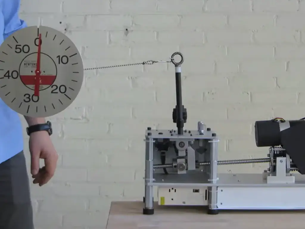
This is what most people picture searching “linear actuator with load cell”: a strain-gauge load cell measures actual force in real time, and a controller adjusts the motor to hold a commanded force. It is the first path that maintains a force rather than merely detecting it. “The load cell provides both static and dynamic force feedback to a PLC, which adjusts the servo motor output in real time” (FUTEK). The two primary approaches are open-loop and closed-loop; closed-loop is the one that needs precision force sensing (FUTEK, futek.com).
This is the right path for pressing, clamping, and test-loading, anywhere a target force must be reached and held. It is also where the real engineering starts: sensor placement, signal resolution, and holding strategy decide whether the loop is a precision tool or an expensive toy (next section).
Path 4: Servo Force Control
At the top sit servo-grade actuators: low-friction, low-backlash designs whose motor current loop is the force sensor. Friction and cogging are so low that the current signal stays faithful even at rest, so no external load cell is needed. That is how direct-drive robots get high-bandwidth force control without bolted-on sensors (PMD, Force Control in Actuators and Robot End Effectors).
The capability is real, and so is the price, an order of magnitude above everything else. If you need millisecond-level force response (robot end-effectors, haptics), this is the path. If you need to press to a force and hold it, a load-cell loop at Path 3 does the job at a fraction of the cost.
| Path | Precision | Cost Range | Fails When |
|---|---|---|---|
| Contact/stall detection | On/off contact only | $ (a few dollars) | Soft materials compress without tripping; no force value |
| Current sensing (open loop) | Dynamic estimate only | $ (PWM + amp) | Static load; non-backdrivable screws |
| Load cell closed loop | True force value, held | $$ (~$2k DIY) to $$$ industrial | Bad sensor placement; low ADC resolution |
| Servo force control | Highest bandwidth | $$$$ | Cost overkill for press/hold jobs |
Here is the map worth memorizing: there are four paths to force control (contact detection, current sensing, load-cell closed loop, servo force control), and each one fails somewhere different. A few-dollar switch detects contact but not force; current sensing measures motion resistance but lies at standstill; a load cell gives a true force value you can hold; a servo loop buys bandwidth most machines never use. Everything below is about choosing among them, then building the choice without tripping the failure modes.
Do You Need Force, or Just Contact?
Before choosing a path, ask the question the SERP never asks: do you need to measure force, or just to know something happened? A robotics thread’s top reply put it best: “Do you really need to measure the force, or do you just need to know the actuator is touching it? Maybe all you need is a switch.”
The 4-Question Self-Test
Does the task need to STOP or REVERSE on contact? → Path 1 (contact/stall detection)
Do you need to sense dynamic resistance (stall, blockage, overload)? → Path 2 (current sensing)
Must you reach AND HOLD a specific force value? → Path 3 (load-cell closed loop)
Do you need fast force response during motion (end-effector, haptic)? → Path 4 (servo force control)
Map your application: pressing, clamping, and test loading all live at question 3, where you set a force and hold it while the material relaxes. A test engineer on the NI forums described it precisely: a closed loop that “maintains a velocity such that the load being reported from the load cell is equal to the expected load.” Contact operations (positioning heads, stop-on-obstacle safety) are question 1.
The cost ladder explains why this matters: a switch is a few dollars, current sensing is nearly free on top of the driver, and a load-cell setup lands around $2k for a hobby-scale build (the budget that surfaced repeatedly in the robotics thread). Industrial closed loops start well above that. If question 1 is your real need, spending Path 3 money on it is the most common budgeting mistake in this category.
One trend is pushing applications up this ladder: force control is migrating from test and robot labs into volume production, in energy storage assembly, PV production, and smart warehousing, as part of the shift from hydraulic to electric actuation. The global electric actuator market is forecast to reach roughly USD 3.3 billion by 2029, growing about 3.7% per year (market research cited by Yahoo Finance, 2025). Force feedback is the feature that makes electric drives credible replacements for hydraulics on press-and-hold jobs.
Building Closed-Loop Force Control
If the checklist put you at Path 3, three details kill more projects than motor selection ever will.
Load Cell: Where It Goes, What Type
The cell must see the force you care about. An inline cell at the rod end measures output force directly (the most accurate option) and is the first to fail in harsh environments, because it takes the same shocks as the rod. A cell at the stationary end (body-to-frame) is simpler and protected, but it sees the actuator’s own friction and inertia on top of the load, so readings skew. The robotics thread debated exactly this trade-off, with rod-end mounting winning where direct measurement matters.
| Mounting | Sees | Accuracy | Weakness |
|---|---|---|---|
| Inline, rod end | Output force only | Highest | Exposed to shocks, side loads |
| Stationary end (body-to-frame) | Load + actuator friction + inertia | Lower, offset shifts with wear | Safe from environment |
| Integrated (inside actuator housing) | Net output force | High | Limited to actuator maker’s integration |
Signal path is the second decision. Most industrial cells output 0–10 V or 4–20 mA into a PLC or motion controller, and resolution matters more than people expect. A 12-bit ADC divides full scale into 4,096 steps; 16-bit into 65,536. An NI engineer steering a test fixture toward the 16-bit board explained why: 12-bit ADCs give “a much better resolution of your force feedback signal” only when you upgrade. At 6,000 N full scale, 12 bits resolves roughly 1.5 N, coarse for a fine press target.
Control Loop: Setpoint, Not Speed
A common beginner error is building a speed loop and calling it force control. The NI engineer corrected his own design on exactly this point: “you don’t need speed control, but force control… load a fixed setpoint and send the start command.” In practice: the controller holds the force setpoint as an outer loop, and the motor simply moves as needed to keep the cell at target, whether extending, retracting, or sitting still against a creeping load.
Signal resolution sets the floor
4,096
steps — 12-bit ADC
65,536
steps — 16-bit ADC
At 6,000 N full scale, 12 bits resolves ≈1.5 N — coarse for a fine press target.
Holding Force Against Creep
“Maintain that force as the thing being pressed will slowly compress over several hours,” an Arduino forum builder describing his digital press. This is the hidden requirement in every press-and-hold application: materials creep, seals relax, and an open-loop controller watches the force sag. Two strategies exist:
- Continuously energized closed loop: the motor keeps adjusting to hold the cell reading. Simple, but the actuator runs warm, and duty cycle becomes the binding spec (many compact actuators are rated 10%, max 2 minutes continuous).
- Self-locking screw + closed loop: a T-type screw holds position without power, so the controller “bumps” the rod forward periodically to restore setpoint. The stepper-driven ball-screw variant does the same with the motor de-energized between corrections, the approach recommended in the press thread for long holds.
Finally, threshold logic: a single absolute force threshold misjudges soft contact, because a soft target compresses slowly. Trigger on rate of change instead. The thread’s analogy: “the only difference between hitting something hard or soft will be the rate of change to the resistance over actuator distance.” If you must distinguish firm from yielding contact, monitor dF/dx, not just F.
Building a closed-loop force actuator? Get the feedback options (reed switch, Hall sensor, signal output) matched to your controller’s inputs.
Discuss your control-loop specWhat to Demand From a Supplier
When you’re ready to buy, force control shifts from a feature question to a spec question. Drive the conversation with numbers, not adjectives:
- Thrust range: the full operating band, not just peak (compact electric actuators run roughly 20 N to 6,000 N)
- Stroke and mounting distance: 25–2,000 mm is a realistic spread; mounting distance decides whether the unit fits at all
- Voltage and speed: 6/12/18/24 V DC common; speed tiers like 20/30/40/50 mm/s are the standard custom options
- Feedback options: built-in limit switches as baseline; reed switch or Hall sensor for position; signal-feedback versions for the control loop
- Environment rating: IP44 to IP65 covers most indoor industrial and medical use
- Verification: what testing does each unit pass before shipping, and can they produce the data report?
Then demand the verification layer: every unit ships with a test record from an aging/performance test, not just sample inspection; certifications (CE, RoHS) are documentable per model; and the maker proves custom-parameter capability with samples before you commit a batch.
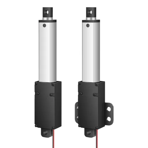
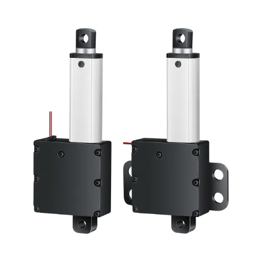
For a concrete reference point, take our own line: Hoodland builds electric actuators from 20 N to 6,000 N with strokes of 25–2,000 mm, 6 V to 24 V voltage options, and standard speed tiers at 20/30/40/50 mm/s. Every model carries built-in limit switches, and feedback options extend to reed switch, Hall sensor, or signal-feedback versions for closed-loop control (electric actuator ranges with built-in limit switches and optional feedback signals). Because we run our own mold, injection, and CNC workshops, custom force, speed, stroke, and feedback combinations are prototyped in-house rather than outsourced (custom force, speed, stroke, and feedback options), and before shipping, every unit passes a 2-hour aging test plus full inspection, with its own data report included. That is the standard to hold any supplier to.
Failure Modes That Kill Force Control
Real failures beat any spec sheet, so here are three documented ones from the field.
Failure 1 — “The external pressure sensor doesn’t work because of the uneven surface of the objects.” A mechanical engineer built contact-stop with an external pressure pad and watched it fail on irregular workpieces. Lesson: force sensing must be integrated at the actuator, not bolted onto the load path after the fact.
Failure 2 — “You can’t measure static load using current as a proxy.” The current-sensing path looked free until a stall-holding application silently lost its force reading. Current is a motion-resistance signal; at standstill it is a lie. If your task holds a load, plan for a load cell or a backdrivable servo from day one.
Failure 3 — “Maintain that force as the thing being pressed will slowly compress over several hours.” A digital-press build with a fixed setpoint watched its target force sag as the workpiece crept. Open-loop “push and stop” cannot hold force; the controller must keep adjusting, or a self-locking screw holds while the loop bumps it back.
When a force-control system misbehaves, run the diagnostic chain in order: re-check the requirement (force or contact? Back to the four-question test), measure rate of change rather than a single threshold, verify sensor placement (rod-end vs stationary-end changes what the reading means), and confirm signal resolution (a 12-bit ADC cannot hold a fine force setpoint no matter how good the cell is). Nine times out of ten, the failure is in one of these four, not in the motor.
The Business Case: Buy a Subsystem, Not a Part
Here is the business reality behind the engineering: a force-control loop is not an actuator purchase, it is a three-part subsystem (actuator + sensor + controller) that must be tuned as one unit. The hobby route proves the point: a DIY assembly lands around $2k before your own tuning hours, and it still fails the static-load test. On a production line the same failure multiplies: every stalled press is downtime, every drifted force is a rejected part.
So the smart procurement move is to buy the subsystem from one supplier who has already tuned it. Demand three things in the RFQ: feedback-interface support (how their actuator’s feedback integrates with your controller, not left as your integration project); verifiable test data (aging tests and full inspection per unit, with reports); and custom-parameter capability (force, speed, stroke, feedback options, the parameters that turn a catalog part into a machine component).
The tailwind is real: electric actuators are displacing hydraulics across assembly and materials handling, with the market growing about 3.7% per year toward USD 3.3 billion by 2029 (market research cited by Yahoo Finance, 2025). Force feedback is precisely the feature that closes the gap with hydraulics on press-and-hold work, so the suppliers who deliver tuned, tested force-control subsystems are the ones capturing that growth. And not every project needs it: if your four-question test landed at “contact detection,” buy the $5 switch and spend the difference elsewhere. Buy force control deliberately, and buy it as a subsystem, not as a part.
If you’re sizing a force-control application and want feedback-interface specifics, talk to us at Hoodland. Our engineers answer within 12 hours, worldwide, and every actuator ships with a 1-year warranty (request a quote or discuss your force-control application).
Spec a Force-Controlled Actuator That Ships Tested
Custom thrust, stroke, speed, and feedback options — every unit passes a 2-hour aging test and ships with its own data report.
Request your actuator specReferences
- FUTEK. “Linear Electric Actuator with Force Sensor | Force Control.” futek.com. https://www.futek.com/applications/linear-actuator-with-force-sensor
- National Instruments (NI) Forum. “Dynamic force control using linear servo actuator + load cell.” forums.ni.com. https://forums.ni.com/t5/Motion-Control-and-Motor-Drives/Dynamic-force-control-using-linear-servo-actuator-load-cell/td-p/1067426
- Reddit r/robotics. “Linear actuator with force sensor.” reddit.com. https://www.reddit.com/r/robotics/comments/1d443tr/linear_actuator_with_force_sensor/
- Reddit r/arduino. “Load cell controlling linear actuator.” reddit.com. https://www.reddit.com/r/arduino/comments/wv75jj/load_cell_controlling_linear_actuator/
- PMD (Performance Motion Devices). “Force Control in Actuators and Robot End Effectors.” pmdcorp.com. https://www.pmdcorp.com/resources/type/articles/force-control-in-actuators-and-robot-end-effectors
- Yahoo Finance. “Global Electric Actuator Market Growth Accelerates…” 2025. https://finance.yahoo.com/news/global-electric-actuator-market-growth-141500129.html
- Hoodland. “Electric Actuators.” thehoodland.com. https://www.thehoodland.com/electric-actuators/
- Hoodland. “Custom Solution.” thehoodland.com. https://www.thehoodland.com/custom-solution/
- Hoodland. “Contact Us.” thehoodland.com. https://www.thehoodland.com/contact-us/
- Hoodland. “Home.” thehoodland.com. https://www.thehoodland.com/
 English
  Chinese