
What Is a Lead Screw Actuator and How Does It Work?
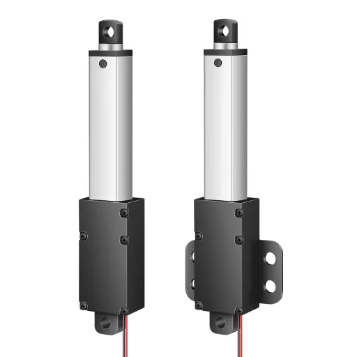
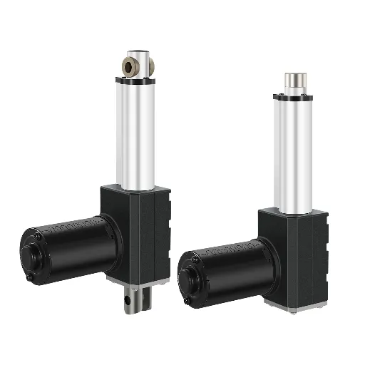
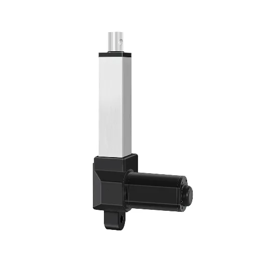
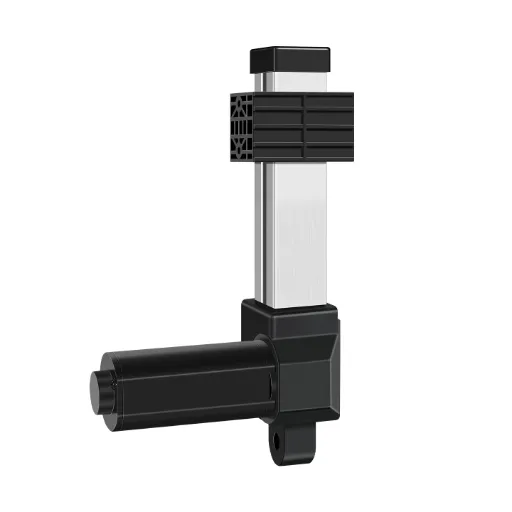
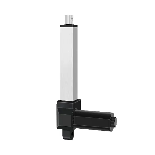
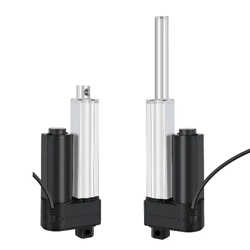
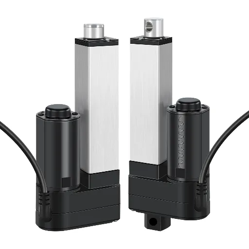
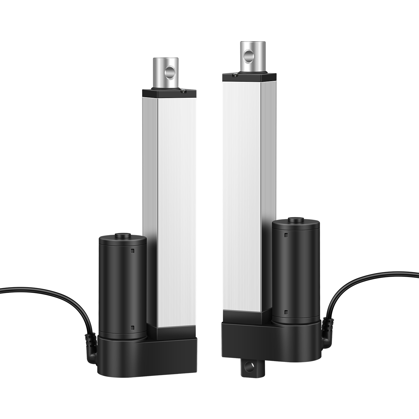
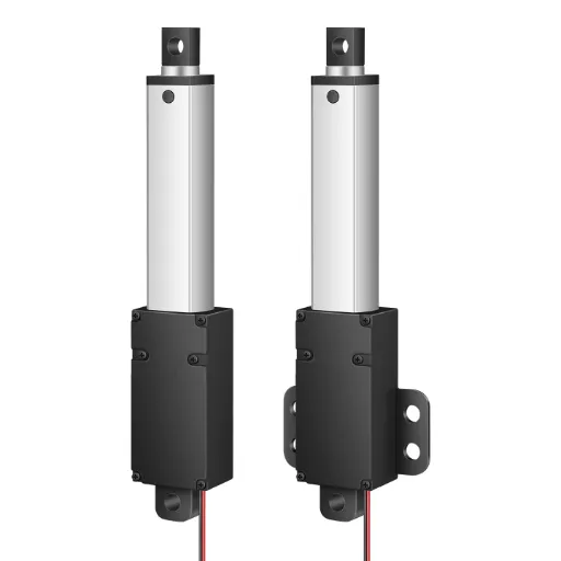
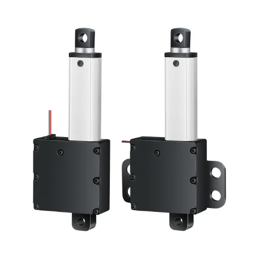
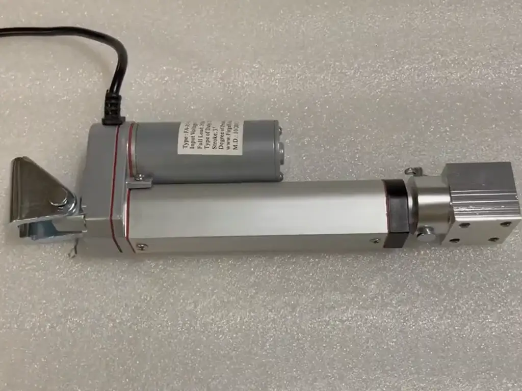
A lead screw actuator is one of the simplest ways to turn rotary motion into linear motion. Inside the housing, a motor (usually DC, often through a gearbox) spins a threaded shaft, and a nut riding on that shaft travels along its length — pushing or pulling the rod with it. Two parts, one motion.
Everything that matters about the design is decided by the geometry of that thread. A finer pitch gives more force at lower speed; a coarser pitch moves faster with less force. That trade-off is the reason the same actuator family exists in many variants rather than one universal model.
Before you go deeper, two details matter. Most industrial actuators come with limit switches built in, so the rod stops itself at stroke ends instead of driving into the housing. And the nut is where design quality shows up first: polymer nuts (POM and similar) run quieter and last longer than metal-on-metal sliding contact, which is why quiet-rated actuators use them.
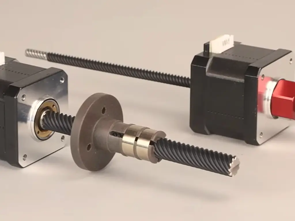
Lead Screw Actuator Types: Trapezoidal, Multi-Start, and Ball Screws
When a supplier talks about a “lead screw actuator,” they usually mean one of three drive arrangements:
Trapezoidal (T-type)
The mainstream choice for standard industrial actuators. Moderate efficiency, good self-locking, tolerant of dust.
Boundary: continuous duty or very high loads.
Multi-start
Two or more thread starts — the nut advances farther per revolution. Faster at the same motor speed.
Boundary: each extra start erodes self-locking.
Ball screw
Rolling elements instead of sliding contact — efficiency above 90% versus roughly 20–48% for trapezoidal screws in dry operation (per igus’s efficiency tests).
Boundary: contamination-sensitive, costlier, back-drives readily.
The motor connection adds a second dimension: direct drive (motor shaft is the screw) or gearbox-reduced (force multiplied, speed divided). Gearbox units are how compact housings reach high thrust without a huge motor.
Which one should you care about? If your application is moderate load, low duty cycle, and dirty or dusty surroundings, the trapezoidal design is usually the right answer — and it is what most off-the-shelf industrial actuators are built around. The efficiency difference matters when you need continuous duty or high speed, which is when ball screws earn their cost.
File this boundary away now: efficiency and self-locking are the same coin. A lead screw assembly that is efficient enough to back-drive (typically 50% efficiency or higher, per PBC Linear) loses the “holds position with power off” behavior that many designers quietly rely on. We will come back to this in the sizing section.
How Lead Screw Actuator Ratings Actually Work Together
This is the section where most design mistakes happen, because catalogs present each number as if it were independent. It is not.
Speed and force are a pairing, not two separate specs
A single actuator model does not have “a force” and “a speed.” It has a force at each speed. Consider a typical 24 V industrial unit:
| Speed (mm/s) | Rated push/pull (N) |
|---|---|
| 5 | 2,500 |
| 10 | 1,200 |
| 20 | 600 |
| 30 | 400 |
| 52 | 300 |
Read it the way the physics dictates: the actuator delivers its full rated force only at its slowest speed. At 52 mm/s you get roughly one-eighth of the slow-speed force. If your spec sheet says “maximum force 2,500 N” and “speed 50 mm/s,” those two numbers may never be simultaneously true — and designing for both at once is exactly how actuators get undersized.
What to do: build your design around the speed you actually need, then read the force rating at that speed. And ask the supplier for the full speed-force table — not the headline numbers.
Push and pull ratings are not automatically equal
The direction question is a real one. Internally, the rod’s thrust bearings determine how much load the actuator can take in each direction, and manufacturers commonly bias the bearing configuration toward compression. In practice, engineers who have worked with common brands from 2,000 N to 10,000 N report that push ratings are usually rated higher than pull. If your application does most of its work in tension — door opening, lid lifting, suspension — that asymmetry is not a footnote; it can cut your usable capacity.
Ask for separate push and pull ratings before you commit, and size to the direction your load actually sees.
Duty cycle: the rating nobody budgets for
Duty cycle is the share of time the motor may actually run. A 10% duty cycle with a 2-minute continuous limit (typical for industrial linear actuators) means the actuator runs at most 2 minutes, then must rest. Continuous-running designs are a different product class.
This is where the interlock bites: force, speed, and duty cycle trade against each other, and so does life. Industry lifespan benchmarks sit around 10,000 cycles under normal use; actuators built with polymer gears and properly matched parameters reach roughly 30,000+ cycles under the same conditions. Push any one of the three — run at max force, max speed, or past the duty limit — and the others collapse faster than the catalog suggests.
What to do: if your device cycles continuously — medical equipment, automation lines, inspection machines — quote duty cycle in the spec, not as an afterthought.
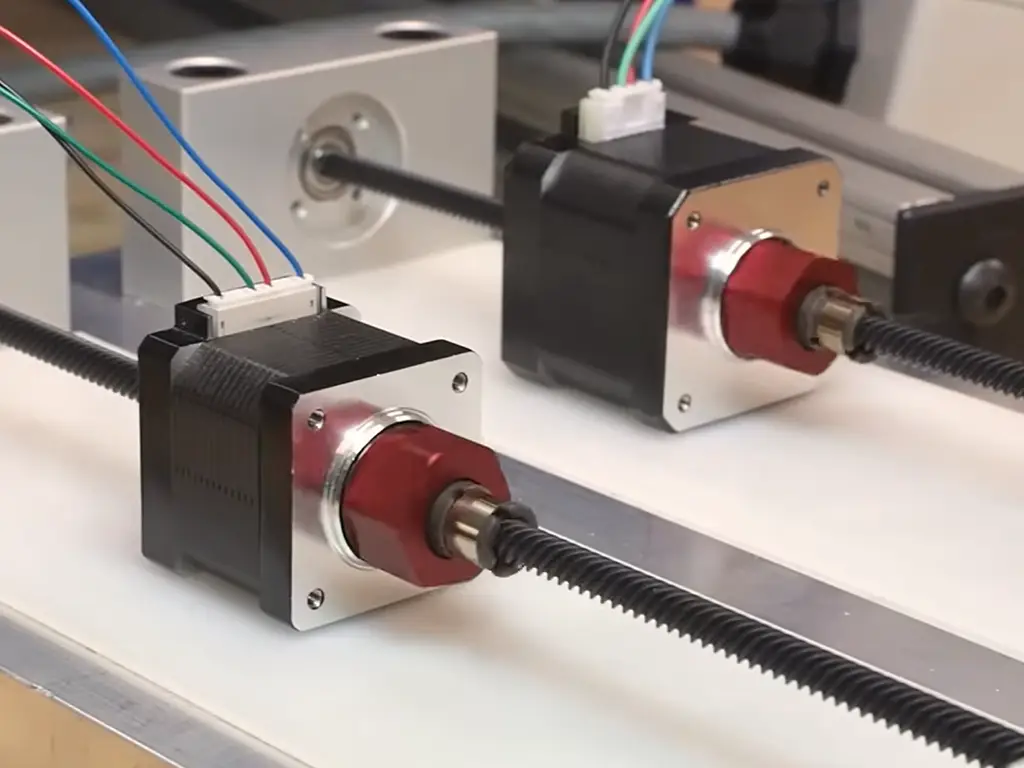
Lead Screw Actuator Sizing: The Calculations That Matter
Sizing a lead screw actuator comes down to four checks. The core relationship is the torque-to-thrust equation:
Torque to thrust
T = F × lead / (2 × efficiency)
Every value deserves scrutiny — starting with efficiency, which vendors quote anywhere from 20% to 80%.
Published efficiency numbers range from 20–48% for trapezoidal screws in dry operation (igus) to 80%+ baselines in some vendor calculators — a spread that changes the required motor torque by a factor of two to three. Treat any single efficiency figure as a claim to verify with the supplier, not a constant to design around.
The other three checks are limits rather than calculations:
- Buckling (column strength). A slender screw under compression behaves like a column: long stroke plus small diameter equals a risk of buckling. Vertical installations are the dangerous case, because gravity puts the full load through the screw shaft.
- Critical speed. Every screw has a natural-frequency limit; beyond it, the assembly vibrates severely. Longer screws have lower critical speeds — a longer stroke may force you to a larger diameter just to run at the speed you need.
- PV value (pressure × velocity). For polymer nuts, the product of contact pressure and sliding velocity must stay under the nut’s PV rating. Exceed it and heat builds up; the nut wears out early even though no single load or speed looked extreme.
Self-locking deserves one more line: because back-driving resistance comes from inefficiency, anything that raises efficiency — multi-start threads, large leads, well-lubricated contacts — erodes it. The same actuator that holds a vertical load perfectly when new can start creeping after a few thousand cycles of wear and lubrication. Do not rely on self-locking as the only safety mechanism on a vertical axis.
| Drive type | Works well when | Switch away when |
|---|---|---|
| Trapezoidal (T-type) | Moderate load, low duty cycle, dusty/dirty environment, budget-sensitive | Continuous duty, very long stroke at high speed, or load above ~6,000 N |
| Multi-start | Faster travel at moderate load, where position-holding is not critical | Vertical loads relying on self-lock, high thrust |
| Ball screw | High speed, continuous duty, high precision, clean environment | Contaminated surroundings, cost-sensitive designs, loads that must hold position without power |
Why Lead Screw Actuators Fail in the Field (and How to Design Around It)
Three failure patterns, all design-stage decisions in disguise
Running at rated max
Trigger: high cycles with no overload sensing — the unit keeps pushing into a stalled load.
Tolerance stacking
Trigger: parallel guides drift even microns — assembly binds and the weak motor stalls.
Duty cycle ignored
Trigger: the actuator runs past its duty limit, overheats, and fails exactly as the catalog predicted.
Three failure patterns account for most field problems, and all three are design-stage decisions in disguise.
Failure 1: running at rated max with high cycles. A documented case: a hot-plate welder ran its actuators near maximum load with a program that did not sense an out-of-position high-load condition; the internal polymer nut gave out because the unit kept pushing into a stalled load. The actuator was fine — the control logic was not. Any application that can stall against a physical stop needs either current sensing, position feedback, or generous derating.
Failure 2: tolerance stacking and binding. A precision lift table built on two parallel rails bound whenever alignment drifted even microns; assembly required shimming, and the weak motor stalled the moment the mechanism bound. The design lesson, confirmed across engineering forums: parallel guides need compliant mounting — fix one rail rigidly, allow the other to float — and keep the lead screw aligned with the travel axis, not offset from it.
Failure 3: duty cycle ignored at the board level. This is the sizing section’s lesson showing up as a field incident: the actuator runs 5 minutes, overheats, and the customer sees premature failure that the catalog’s 10% duty rating already predicted.
Design-stage checklist
Add overload sensing or position feedback to any load that can stall.
Budget one compliant axis in every multi-guide arrangement.
Quote duty cycle against actual cycle time, not intuition.
Leave rated-force margin for any high-cycle application.
Turning Your Design into a Spec: What to Ask a Supplier
Once the calculations are done, the work moves from your desk to a supplier’s — and this handoff is where vague parameters become expensive surprises. A complete lead screw actuator spec covers more than force and stroke.
What a complete spec sheet contains
Voltage (6–24 V DC typical), rated force at your operating speed and in the direction you need, stroke (25–2,000 mm is the practical industrial range), speed at no load, duty cycle, IP rating (IP44–IP65 covers most indoor industrial and medical uses; higher needs enclosure), operating temperature, cable length, mounting, connectors, and feedback — limit switches, reed switches, or Hall sensors depending on what your controller expects. Add certifications relevant to your market: CE and RoHS are baseline for most; explosion-proof ratings (Ex-rated) matter for energy storage and hazardous zones.
Complete spec sheet checklist
Voltage — 6–24 V DC
Rated force — at your operating speed, in the direction you need
Stroke — 25–2,000 mm practical range
Speed at no load
Duty cycle — and the continuous-run limit
IP rating — IP44–IP65 for most indoor uses
Operating temperature
Cable length, mounting, connectors
Feedback — limit switches, reed switches, or Hall sensors
Certifications — CE, RoHS, and Ex-rated where applicable
The bracketed ranges are typical industry spans — final values follow your device’s actual requirements.
The three questions that separate good suppliers from the rest
Ask every candidate supplier these three questions, and judge the answer, not the brochure:
- “Can I have the full speed-force table?” Not the headline max: the paired values.
- “What is the duty cycle and continuous-run limit?” The actual numbers, not “long life.”
- “What is the measured thrust versus the label rating?” Some manufacturers publish conservative numbers; a supplier who invites verification is telling you something about their confidence.
Custom specs, lead times, and where the limits are
Customization is where a design becomes a product. Practical industrial actuators are made to order across voltage (6–24 V), force (20 N–6,000 N), speed (standard steps of 20/30/40/50 mm/s), stroke, IP protection, cable length, and interfaces — and one-off builds are common, with no minimum order quantity in many factories. Realistic lead times: 3–7 days for standard custom builds, up to 15 days for complex changes like motor swaps, and 1–3 days for samples. At Hoodland, we build custom lead screw actuator configurations from voltage and force through stroke, speed steps, mounting, and feedback, with no MOQ — one unit is accepted — and we share the speed-force pairing data for the exact model you are quoting, so the spec you sign matches the unit you receive. Customization has a physics boundary, though: a supplier that promises anything will deliver nothing reliable. A serious one tells you when a request violates basic mechanics and proposes a workable alternative instead.
Verify these three things before you commit
The full speed-force table
The duty cycle and continuous-run limit
Measured thrust vs. label rating
The Business of Design: Rating Transparency as a Supplier Test
Step back and notice what the last three sections have in common. Every warning from the last three sections (the speed-force pairing, the direction asymmetry, the duty cycle trap, the efficiency spread, the self-locking erosion) is a piece of information that a spec sheet could provide and a brochure usually does not. The suppliers who give you these numbers unprompted are not being generous; they are transferring the risk of failure from your site to their own reputation. The ones who offer only single-point maximums are asking you to carry that risk.
So add one more filter to your supplier selection, and apply it before price: require the interlock data. A vendor’s willingness to show you where their product stops working is the most reliable quality signal in this industry. When the data is transparent, the engineering conversation starts on facts; when it is not, you will discover the boundary at your own site — usually on a production line, at the worst possible moment.
Get a Custom Lead Screw Actuator Quote
Send your speed-force table, duty cycle, and stroke. We will match a build — and show you the paired data before you commit.
Request a Custom QuoteReferences
- igus. “Efficiency.” 2021. blog.igus.eu
- PBC Linear. “What Is Lead Screw Efficiency?” pbclinear.com
- Linear Motion Tips. “Lead Screw Sizing in 4 Steps.” linearmotiontips.com
- Machine Design. “Choosing the Best Lead Screw for a Linear Motion Application.” 2009. machinedesign.com
- Eng-Tips. “Lead Screw Setup Is Binding… Need a New Design.” eng-tips.com
 English
  Chinese