
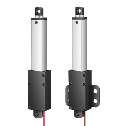
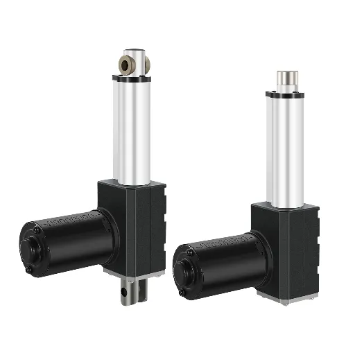
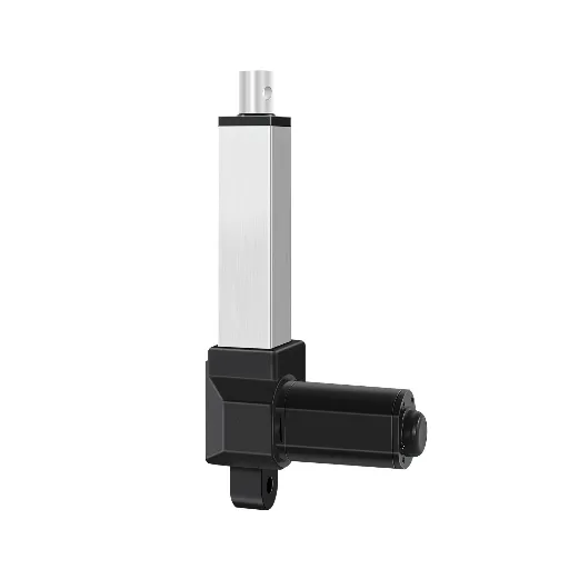
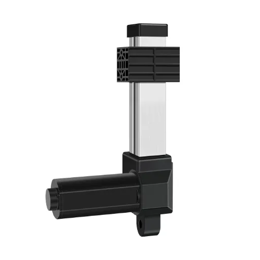
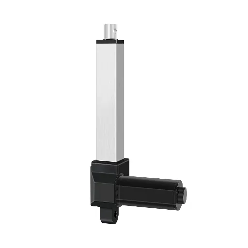
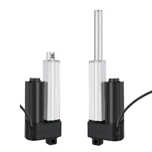
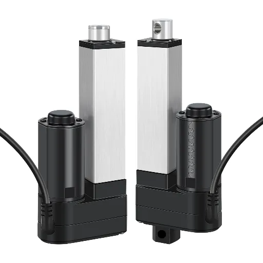
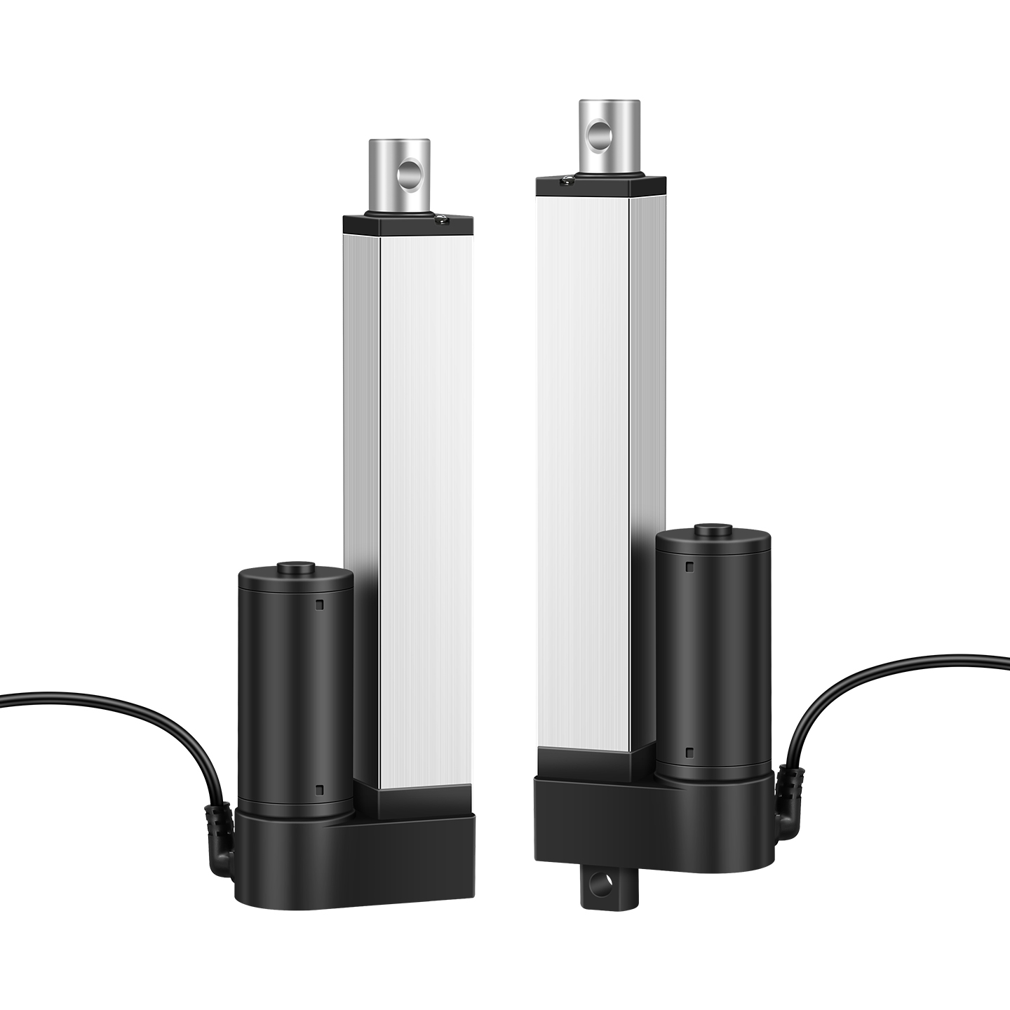
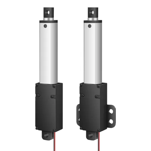
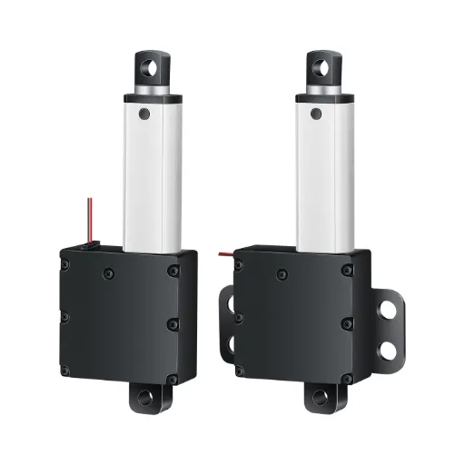
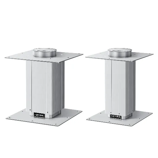
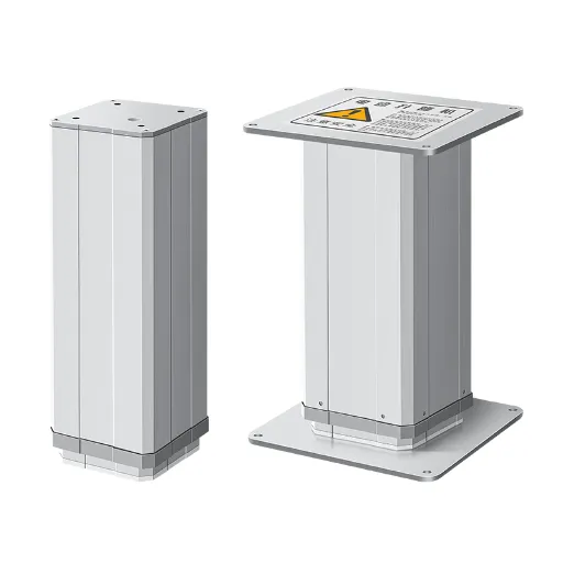
“Position” is the most overloaded word in the linear actuator world, and the most expensive to get wrong. Search for “how to calculate linear actuator position” and you will find two very different answers wearing the same label. One is a geometry problem you solve before you buy: how long the stroke must be and where the actuator mounts. The other is a measurement problem you solve when the system runs: how the controller knows where the actuator is right now. Both matter, and both are solved differently. Confuse them, and you end up with an actuator that either cannot reach its target or cannot tell you where it is.
This guide answers both questions in order. First the geometry that sizes the actuator, then the feedback systems that give it positional awareness, and finally what to ask a supplier so the unit you receive actually answers both.
Where Position Information Comes From: The Four-Layer Map
Before any calculation, it helps to see the full landscape. Position information arrives from four sources, each building on the previous one:
| Layer | What it is | How it works | Who relies on it |
|---|---|---|---|
| 1. Geometry derivation | Sizing stroke & mounting points from installation dimensions | Trigonometry before purchase, no electronics | DIY builders, cabinet, hatch and lift projects |
| 2. Built-in feedback | Sensors integrated at the factory | Potentiometer, Hall, reed or optical signal readable by a controller | Home-automation and industrial OEM buyers of stock models |
| 3. External sensors | Sensors added to an existing actuator | Encoder, LVDT or string pot mounted on shaft or rod | Engineers retrofitting units without feedback |
| 4. System-level positioning | Homing, power-loss recovery, synchronization | Controller logic on top of feedback data | Industrial equipment: storage systems, robotics, medical devices |
The first layer costs nothing and is done on paper. The last layer is where industrial equipment actually lives, and it is the layer almost no guide covers. Each section below climbs one rung of the ladder.
How to Calculate Actuator Position from Geometry
For a straight push or pull, the required stroke is simply the distance the load must travel, plus margin. Measure the travel, add buffer, and the stroke is defined. The math only gets interesting when the actuator mounts at an angle, which is the rule rather than the exception for hatches, lids, doors and panels.
For hinged applications, treat the mechanism as a triangle formed by the hinge, the actuator’s fixed mount, and its moving mount. The law of cosines gives the distance between the two mounting points at any opening angle: D² = A² + B² − 2AB × cos θ, where A and B are the distances from the hinge to each mount. Your required stroke is the distance between mounts at full open minus the distance at full closed. If you cannot measure those two positions directly, hang a string between the mounting points in each position and measure the difference, this “string method” absorbs every tolerance the formula misses.
When the actuator is angled away from the direction of travel, stroke demand and effective force scale together:
| Mounting angle | Stroke multiplier | Effective force delivered |
|---|---|---|
| 0° | 1.00× | 100% |
| 15° | 1.04× | 97% |
| 30° | 1.15× | 87% |
| 45° | 1.41× | 71% |
| 60° | 2.00× | 50% |
A 60° mount doubles the stroke you need and halves the force the actuator can apply along the load axis. Both consequences come from the same cosine factor, which is why manufacturers’ sizing guides publish the two side by side (Firgelli Automations, “Calculating the Exact Linear Actuator Stroke Length,” 2026). Two further rules keep geometry from biting later: never run the actuator to its hard stops, leave 10–15 mm of unused stroke at each end, and 20–25% extra for applications cycling thousands of times a year; and remember: the fully retracted unit is roughly its stroke plus 100–200 mm. Confirm that collapsed length fits your space before ordering.
Do You Actually Need Position Feedback?
Geometry tells you how far the actuator can reach. Feedback tells the system where it is along that reach at any instant. The question “do I need it?” has a sharp decision rule, three situations where the answer is forced, and a trend that is quietly settling the debate for you.
The Decision Rule: Three Ways to “Know” Position
Every actuator “knows” its ends by default: limit switches at full extension and retraction cost little and cover most furniture, cabinet, and simple hatch applications. Some controllers estimate position by run-time or current draw, which is cheap and unreliable in equal measure. Only position feedback, a sensor signal proportional to actual position, supports intermediate stops, memory positions, closed-loop control, and synchronization.
The test is one question: does your device need to stop anywhere between the two ends, or remember more than one position? If no, limit switches are enough and feedback is optional money. If yes, feedback is not a feature, it is the mechanism your control scheme is built on.
Limit Switches
Stops at both ends. Covers most furniture, cabinets and simple hatches.
No stops in between
Timer & Current Sensing
Estimates position from run-time or current draw.
No real position signal — drifts under load
Position Feedback
Reads actual position continuously from a sensor signal.
Required for intermediate stops, memory & sync
When Feedback Becomes Mandatory
Three scenarios make feedback non-negotiable:
- Synchronization. Two actuators driving one platform (a lift desk, a wide hatch) must extend in lockstep. Without feedback, tiny manufacturing differences in motor speed accumulate until one unit bottoms out while the other is still traveling, twisting and binding the structure. Feedback is what lets a controller keep both units matched.
- Memory positions. A bed, sofa, or workstation that returns to preset heights stores those positions as sensor values. No feedback, no memory.
- Closed-loop positioning. Any process that holds or repeats a position, automated storage, inspection, robotics, reads the sensor and corrects continuously.
The Trend: Feedback Is Moving from Option to Default
The direction of travel is unmistakable. Industry research sizes the global electric actuator market at USD 18.04 billion in 2025, reaching USD 99.01 billion by 2035 at an 18.35% CAGR (SNS Insider, “Electric Actuator Market Report,” 2025). The same report names “smart actuators with integrated force and position sensors” among the primary growth drivers, alongside Industry 4.0 networking such as IO-Link and PROFINET. Buyers increasingly quote feedback as a basic specification rather than an option; the sensor content is already built into the market’s growth story.
Choosing the Right Feedback: Sensors Compared
Once feedback is on the table, the next question is which sensor. Six types cover the practical spectrum: four built in at the factory, two (plus variants) added externally. They differ on exactly three axes that matter: accuracy, cost, and what happens when the power goes out.
Built-in Feedback: The Four Factory Options
Potentiometer — a wiper riding a resistive track, converting position to resistance, read as voltage. Cheapest option, and it physically remembers its position when power is lost; the wiper stays where it stopped. Its weaknesses: a contact that wears in vibration and dusty environments, and accuracy limited by track linearity and the analog-to-digital converter reading it (TiMOTION, “Electric Linear Actuators With Feedback Sensors,” 2021).
Hall effect — a magnetic field sensor counting motor revolutions digitally. Preferred where control is digital and synchronization matters, since the signal is a clean pulse train. Unlike a pot, it forgets position on power loss: the controller has to re-establish a reference, usually by homing. No contact means no wear.
Reed switch — a hermetically sealed magnetic switch. Best for end-of-stroke detection and simple zone feedback; extremely long mechanical life (millions of cycles) because there is no contact to wear.
Optical — a light-blocking wheel generating pulses as the screw turns. High resolution and digital output, at higher cost and sensitivity to oil and dust.
External Sensors: Adding Feedback to an Existing Actuator
If the actuator is already bought without feedback, three retrofit paths exist. An incremental encoder on the motor shaft counts rotations and converts them to linear distance. Cheap and accurate, but relative: it also forgets its position on power loss and needs homing. An absolute encoder remembers position through power loss, at a price; on one industrial forum, an engineer argued the absolute encoder was “probably cheap relative to the damage you’d do from a crash.” An LVDT measures position directly with contact-free, extremely high accuracy, but with short travel and high cost, reserved for precision rigs, not hatches.
The cost math is real. A first-year engineering student shopping for 20–24 mini actuators found feedback versions at USD 70–80 versus USD 29 for bare units, and chose to add encoders himself. The real cost moved into wiring, calibration, and debugging 24 axes (Reddit r/AskRobotics, 2024). For one or two units, buying feedback built-in is nearly always cheaper than retrofitting.
The Decision Matrix
| Sensor | Accuracy | Power-loss behavior | Relative cost | Best for | Fails when |
|---|---|---|---|---|---|
| Potentiometer | Medium (linearity-limited) | Remembers position | $ | Budget position control, memory positions | Vibration, dust, extreme temps |
| Hall effect | High (digital) | Forgets; needs homing | $ | Digital control, synchronization | Power-loss recovery needed, shock |
| Reed switch | End/zone detection | Remembers switch state | $ | Limit and zone detection | Continuous position, high resolution |
| Optical | High | Forgets; needs homing | $$ | Precision counting | Oil, dust, contamination |
| Incremental encoder | High | Forgets; needs homing | $$ | Retrofit, cost-sensitive precision | Absolute position after power loss |
| LVDT | Very high | Remembers position | $$$ | Precision rigs, short travel | Long strokes, tight budgets |
After a Power Cut, Some Sensors Remember
REMEMBERS
- Potentiometer — the wiper stays where it stopped.
- Position survives the outage.
FORGETS
- Hall sensor · Incremental encoder — the controller loses the reference.
- It has to home again after power returns.
Your homing strategy starts here.
What Goes Wrong: Failure Modes from Real Installations
Every failure below is a real post from a real build. Each cost its owner days or dollars; each is avoidable by one check.
Electrical failures are the loudest, but the failures that kill projects are usually mechanical.
When the mechanism beats the sensor, the next mistake is usually financial.
Retrofit economics push builders toward one-off units, which is where the next failure moves up to system level.
And when homing is settled, component selection brings its own traps.
Every one of these failures was caught after the fact, which is why the five questions in the next section belong on the purchase order, not the debug bench.
Buying Feedback-Ready Actuators: What to Ask Your Supplier
If you are a manufacturer integrating actuators into equipment, storage systems, robotics, medical devices, new-energy infrastructure, the purchase order is where geometry and feedback finally meet. Five questions turn a vague “with feedback” into a spec you can verify:
- Which feedback type? Potentiometer, Hall, reed, or optical, ask for the actual option list, not “feedback available.”
- What output signal? Analog voltage/resistance, digital pulses, or switch signals. Your controller’s input defines the answer, and the supplier should match it.
- What happens on power loss? Position remembered, or lost and requiring homing? This decides your power-on sequence and is the single most skipped question in RFQs.
- What is the synchronization story? For dual-actuator systems, does the supplier offer matched units and a control scheme, or is synchronization your problem to solve?
- What does the option cost? The price increment and lead-time impact of adding feedback should be stated up front, in writing.
None of this protects you from the earlier mistakes: feedback specifications cannot rescue a miscalculated stroke, and no sensor fixes mechanical backlash. But treated as a checklist, these five questions convert feedback from a line item into a designed-in capability, which is the difference between an actuator that moves and an actuator that knows where it is.
When the option list matters, our IP1200 and IP3000X series ship with a built-in limit switch and optional reed-switch, Hall-sensor or switch-signal feedback, and voltage, force, speed and stroke are customizable with no minimum order quantity. See our custom feedback and signal options or contact us with your requirement sheet.
Spec Your Feedback-Ready Actuator
Send us your stroke, feedback type, output signal and duty cycle — we’ll confirm the option list, lead time and cost in one reply.
Send Your Requirement SheetReferences
- SNS Insider. “Electric Actuator Market Size, Share & Forecast, 2035.” 2025. snsinsider.com
- Firgelli Automations. “Linear Actuator Stroke Length: Calculate What You Need.” 2026. firgelliauto.com
- Reddit r/AskRobotics. “How to Add Position Feedback to a Mini Linear Actuator.” 2024. reddit.com
- Eng-Tips Forum. “Need to Home to a Middle Position.” 2011. eng-tips.com
- Arduino Forum. “Problems Getting Linear Actuator With Feedback Pot to Work.” 2022. forum.arduino.cc
- Reddit r/AskEngineers. “How to Use a Potentiometer to Measure Linear Actuator Position?” 2023. reddit.com
 English
  Chinese