
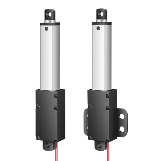
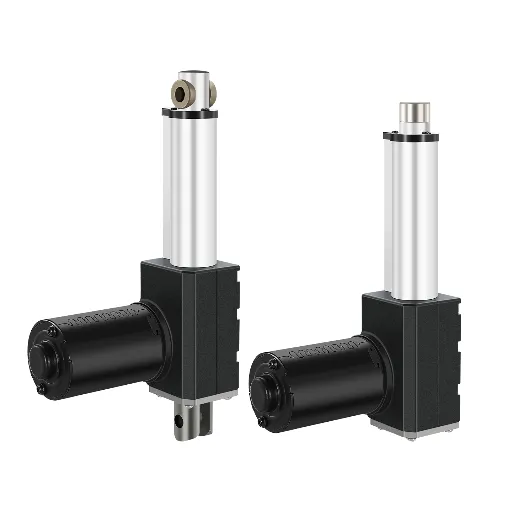
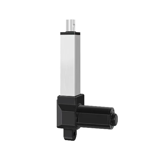
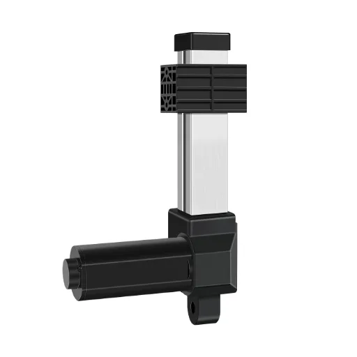
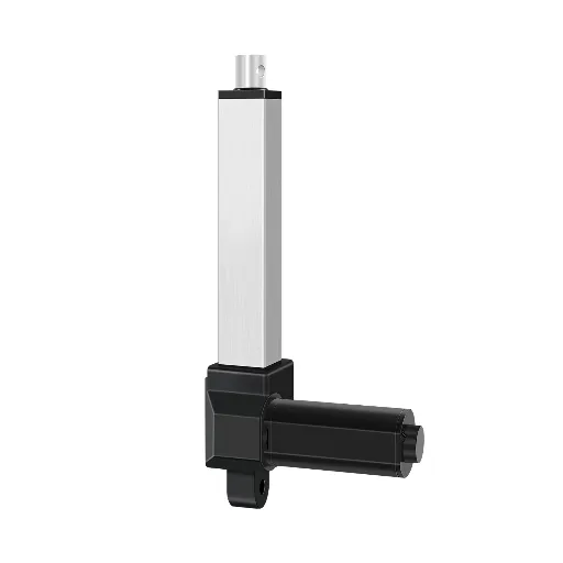
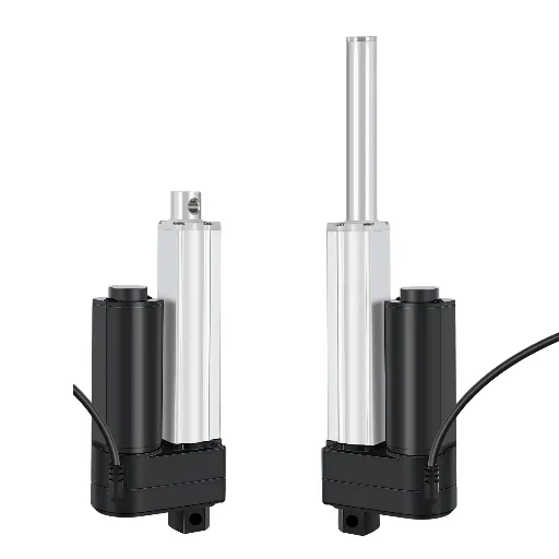
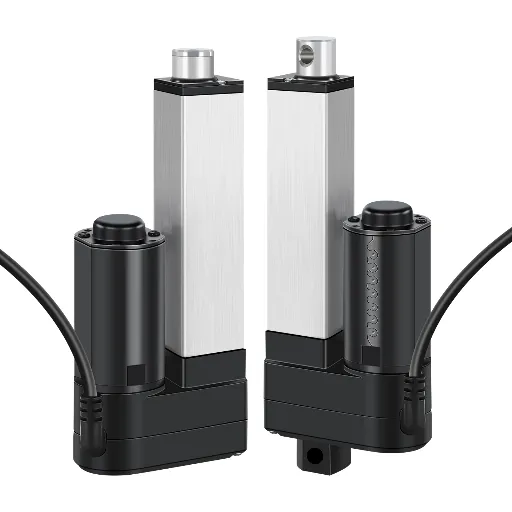
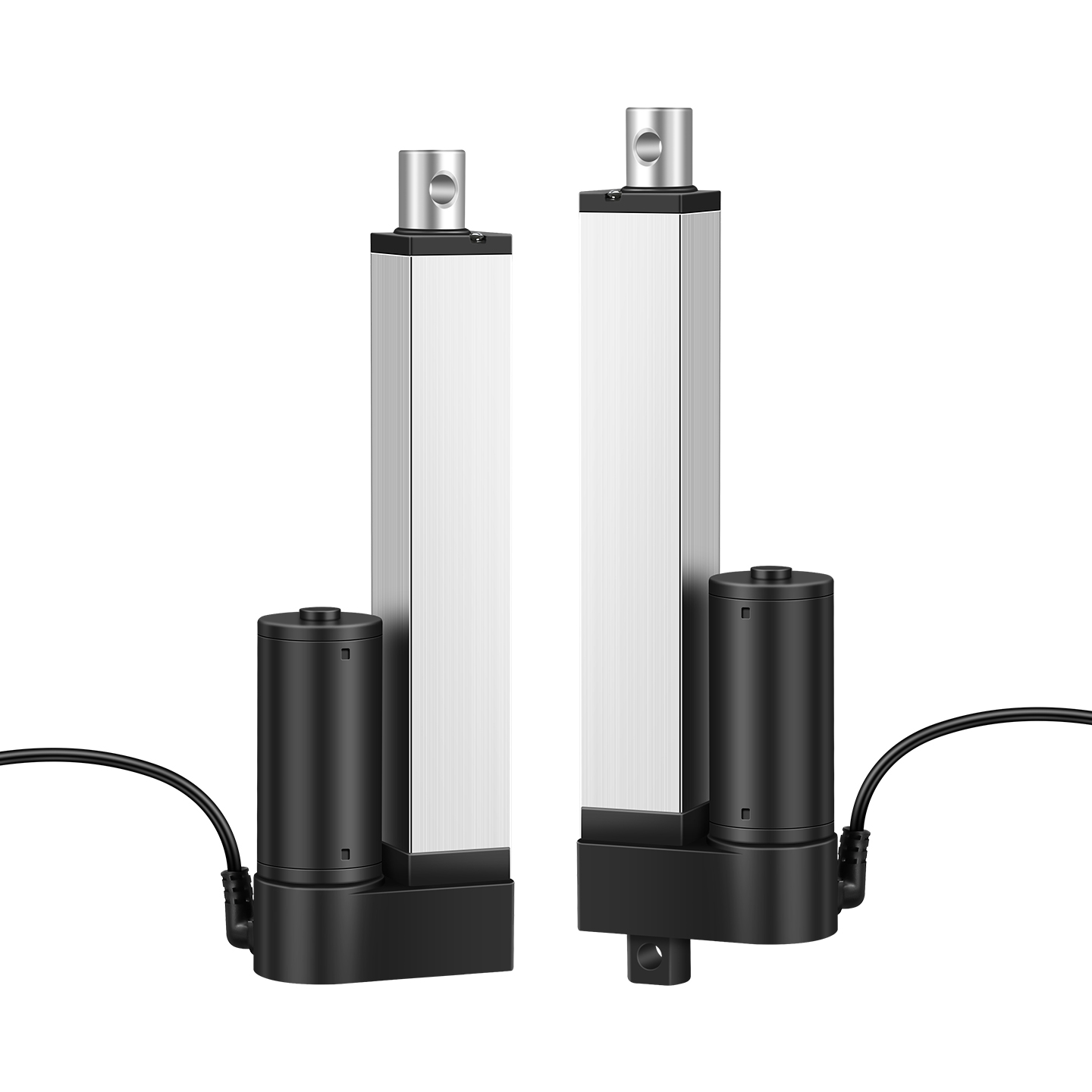
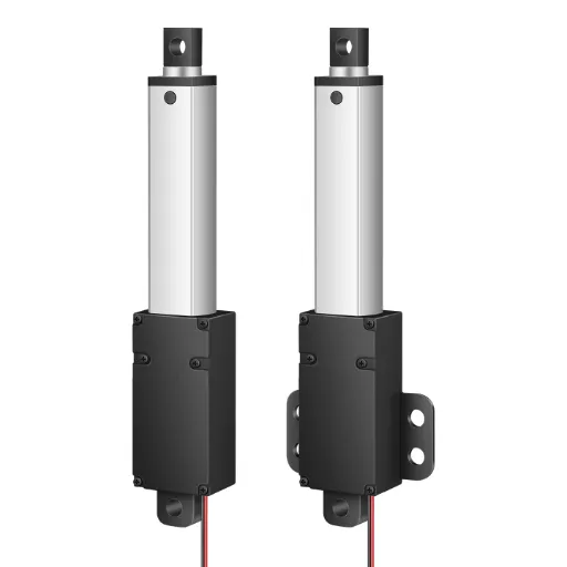
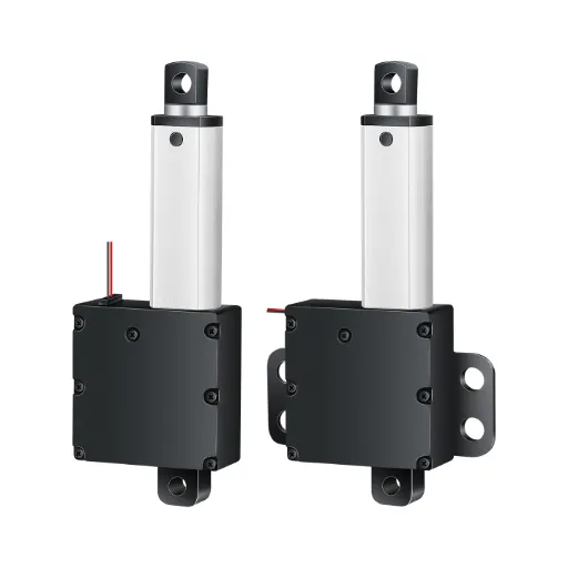
A 12V linear actuator that takes nine seconds to extend feels endless when you are watching it. So you Google “how to make a linear actuator faster,” and you get a list: raise the voltage, change the gear ratio, swap the lead screw, add a controller. Try them, and the actuator gets faster, until one day it doesn’t move at all: it burns out mid-cycle, or it stalls under a load it used to lift easily.
Here is the thing almost every guide leaves out: every way to make a linear actuator faster takes something back. Speed is not a knob you turn in isolation. This guide walks through the five standard methods, what each one actually costs you, and, if you are building a product around this actuator, the four numbers you should give your supplier instead of reaching for a screwdriver.
Where Actuator Speed Actually Comes From
Before touching anything, it helps to see the speed formula, because every trick below is just editing one of its three variables:
Linear speed = motor speed × lead screw pitch ÷ gear reduction
In practical terms: a motor spinning at 3,000 rpm, a 2 mm lead screw, no gearbox. That combination produces roughly 100 mm/s of linear travel (3,000 ÷ 60 × 2). Raise the motor speed, and linear speed rises. Increase the lead pitch to 4 mm, and it doubles. Change the gearbox ratio, and you trade in the other direction.
That is the entire mechanical reality of a linear actuator. Everything called “speeding it up” is a way of touching one of those three numbers. Each touch changes something else downstream: torque available at the output, current drawn from the supply, heat in the motor, and wear on every loaded component.
Five Ways to Make a Linear Actuator Faster — and What Each One Costs
| Method | What it changes | Treats the symptom or the design? | What it costs you |
|---|---|---|---|
| Raise input voltage | Motor speed | Symptom (the quick fix) | Lifespan; heat; warranty |
| PWM / speed controller | Effective duty cycle | Symptom (tune, not speed-up) | Nothing; caps at the motor’s natural speed |
| Change gear ratio | Gear reduction | Design (redesign the drive) | Output force, in direct proportion |
| Bigger lead screw pitch | Lead pitch | Design (redesign the drive) | Required motor torque; stall risk |
| Swap the motor or drive type | Motor + transmission | Design (new system) | Cost; mounting; control complexity |
Raise the input voltage. The cheapest, most tempting fix. Feed an 18V supply to a 12V actuator and it runs roughly 30–40% faster. A Facebook-group user measured 20% at 15V. The catch: brushed DC motors are designed around a nominal voltage. Push beyond it and you get more heat, more wear, shorter life. Actuator manufacturers state it plainly: increasing the operating voltage “will more than likely decrease the lifespan of the unit.” You are borrowing tomorrow’s life to pay for today’s speed.
Add a PWM speed controller. A controller varies the average voltage, which changes effective speed. This is a tuning tool, not a speed-up tool: it cannot make the actuator go faster than its motor’s natural speed at rated voltage. Use it when you want less speed, smoother starts, or matched movement across multiple units, not when you want more.
Change the gear ratio. Inside the actuator, a gearbox trades motor speed for torque. Re-gearing for a higher output speed hands some of that torque back. The trade is mechanical and honest: the speed–force product stays roughly constant, so every 10% of speed gained is force lost.
Swap to a higher-pitch lead screw. This is the method igus recommends for screw-driven actuators: going from a 10×2 pitch to a 10×10 moves the carriage four times farther per revolution. But a steeper pitch multiplies the torque the motor must deliver to move the same load. If the motor cannot supply it, the actuator stalls, stalls again, and eventually overheats. Higher pitch also raises free-running speed toward the point where long screws start to whip and vibrate.
Replace the motor or the whole drive. For big jumps in speed (say, from 30 mm/s to 300 mm/s), you are no longer tuning, you are redesigning. New motor, new gearbox, new screw or belt, new limit switches, new current protection. At this point the actuator is a custom part, and it is time to talk to a manufacturer rather than a parts bin.
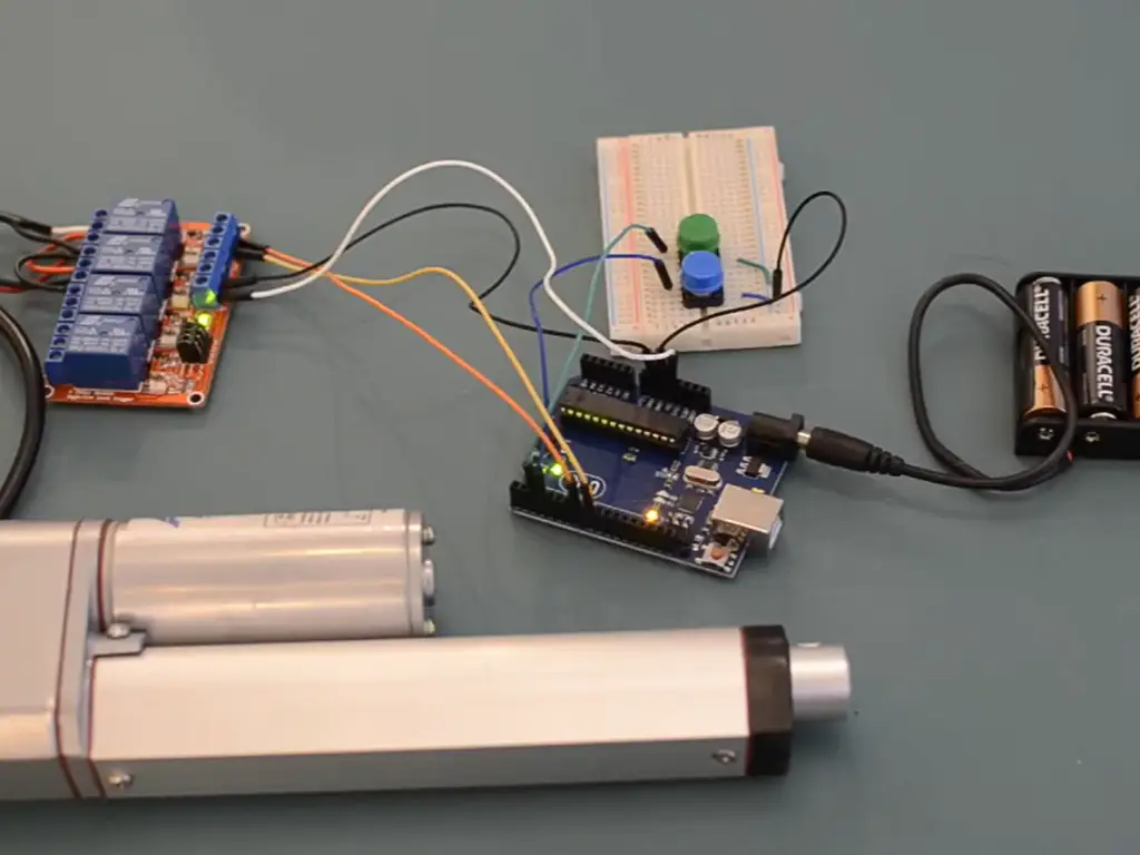
Watch: Linear Actuator Speed Upgrade Demonstration
A practical demonstration of linear actuator speed modification and the performance trade-offs involved.
Tune-Up or Redesign? Deciding What Your Actuator Actually Needs
How do you know which of those five you should reach for? Ask four questions before you touch anything:
Before you touch anything: four questions
- How much faster do you actually need? Twice as fast, or 10%?
- What fraction of rated force is your load? At 20% of rating you have room; at 80% you have none.
- How often does it run? A few cycles a day, or hundreds?
- Do you have hard limits on noise, precision, or life? Medical and indoor products do.
The first question matters more than people expect, because “fast” has no single definition in this industry. An actuator’s speed depends entirely on what it was built for. That is why vendor numbers look contradictory. One manufacturer quotes 0.333 m/s as a screw-driven maximum; another sells “high-speed” units at 9 inches per second (≈230 mm/s). A robotics builder posts on a forum that they cannot find anything fast enough at 350 mm/s. None of them is wrong; they are answering for different application tiers. Match the tier to your application before matching the number.
The other reason to stop and decide: the demand for speed is not staying still. The linear actuator market was valued at $52.7 billion in 2023 and is projected to reach $94.3 billion by 2030 across all actuation technologies (Grand View Research, 2024). Industrial automation (storage, sorting, robotics) is the fastest-growing slice, and faster cycle times are what buyers ask for first. “High speed” is quietly moving from an option to a baseline requirement.
Where “fast” lives in your application
If your answers to the checklist put you in “tune” territory, the first two methods are enough. If they put you in “redesign” territory, keep reading. The next section is about what the redesign actually costs, in numbers.
The Speed–Force Tradeoff, Quantified
The power math: why speed and force trade places
Here is the number that changes how you think about this. Mechanical power is force times velocity:
P = F × v
Within the motor’s power envelope, speed and force trade places in direct proportion. A concrete example: an actuator rated 50 mm/s at 600 N, asked to run at 100 mm/s with the same motor, will deliver roughly 300 N at that speed, before efficiency losses make it worse. Double the speed, halve the force, and the second half of the math is worse than the first.
The speed–force rule
Every improvement in speed is a withdrawal from force, duty, or lifespan. Speed is never free.
This is why the “bigger lead screw” trick has a hidden bill. A 10×2 to 10×10 pitch swap quadruples travel per revolution and quadruples the torque the motor must develop for the same load. Unless the motor has that torque in reserve, you get a faster actuator that stalls under loads it used to carry. Online speed-vs-force calculators (Firgelli’s speed–force tradeoff calculator, 2026) exist precisely because this relationship is where most failed conversions happen.
Beyond the motor: current, duty cycle, and precision
Speed does not only touch force. It also touches three things engineers check before signing off:
- Current. Starting current on a stalled or accelerating brushed motor runs 2–5× rated. Higher target speed means longer acceleration ramps and bigger peak currents, which means the supply, the controller, and the wiring all need headroom they may not have.
- Duty cycle. Duty cycle is the fraction of time the actuator is allowed to run. It exists because motors shed heat during off-time. Push speed up and you push heat up; a unit rated 10% duty (say, 2 minutes continuous) becomes a unit that overheats if you run it harder. Faster movement plus unchanged cycle count means more heat per hour, so the duty rating has to shrink.
- Precision. Position accuracy and speed are linked through the control loop. Limit switches and simple end-stop control tolerate speed changes poorly; encoder or potentiometer feedback handles them better but costs more. If your application needs repeatable positioning at a new, higher speed, budget for a feedback upgrade, not just a faster motor.
When “Faster” Requires a Supplier, Not a Screwdriver
So when does the correct answer stop being “modify” and become “have it built”?
Four signals:
- You need more than ~50% more speed. Beyond that, you are re-matching motor, gearbox, and screw together, which is what a manufacturer does, not what a bench does.
- You have hard limits on noise, life, or certification. Medical, indoor, and energy-storage products carry noise ceilings and lifecycle requirements that DIY voltage-raising will silently violate.
- It runs a lot. High cycle counts amplify every design compromise. A few hundred cycles a day is where “probably fine” stops being good enough.
- You need feedback or protection features (limit switches, position feedback, thermal cut-off, ingress protection), integrated rather than retrofitted.
A capable supplier will not sell you a single speed. They will show you a range of speed–force pairings engineered as a set: no-load speeds stepping from 4 to 150 mm/s, with force falling in the opposite direction (150 N down to 7 N in one common series), limit switches built in, and a duty rating stated next to every number. When you find that, you have found the redesign path. When you find a catalog page with one speed listed, you have found the DIY ceiling.
If any of those four signals hit home, your actuator is a specification problem — and specifications are our job.
Send Us Your Four NumbersWhat Breaks When You Push Speed: Failure Modes and Boundaries
The failure modes of speeding up
Four failure patterns show up again and again in forum threads, service logs, and supplier RMA reports:
Over-voltage burn-out. The most common failure, and the one every guide that says “just raise the voltage” fails to mention. One manufacturer’s warning, that increased voltage “will more than likely decrease the lifespan of the unit” (Actuonix, 2025), is the engineering view; the hobbyist who measured 20% more speed at 15V is describing the first three weeks, not the lifespan.
Screw whip. Long lead screws at high speed start to whip: they flex and vibrate like a jump rope. The threshold depends on screw length, diameter, and speed; push a long-stroke screw past its critical speed and you get vibration, noise, and rapid wear of the nut and bearings. This is the physical ceiling on the “bigger pitch” method.
Hard-stop impact. Faster extension with limit switches that were tuned for slow approach means the carriage slams the end stop. Engineers on professional forums have said it bluntly: a cylinder or actuator “banging a slide against a hard stop” is not a speed solution. It is a fatigue test for the whole frame. Impact loads are multiples of static load.
Multi-actuator drift. Wire four actuators in parallel, and they will not extend at the same speed. Brushed DC motors differ slightly unit to unit, and load imbalance compounds it. A builder on the Arduino forum (moving at different speeds, 2021) hit exactly this: four identical units, four different speeds, no synchronization possible without position feedback. Speeding them up only widens the gap.
When each method stops being a good idea
The boundary matrix below is the honest version of the advice list: when each method works, and the specific check before you rely on it:
| Method | Works when | Stops working when | Check before relying on it |
|---|---|---|---|
| Raise voltage | Small gain (≤20%), low duty, bench use | Continuous duty, medical/indoor, warranty matters | Motor voltage rating margin; thermal cut-off present? |
| PWM controller | You want slower, smoother, or matched motion | You need more than rated speed | Duty-cycle rating of the controller vs your cycle |
| Gear ratio change | You have force in reserve at the shaft | Load is already near rated force | Recalculate force at new speed (P = F×v) |
| Bigger lead pitch | Short stroke, low load, plenty of motor torque | Long stroke (whip), near-rated load (stall) | Screw length-to-diameter ratio; motor torque curve |
| New motor/drive | Any target speed, done as a design | Nothing; just cost and time | Vendor spec sheet lists the speed–force pairing you need |
Sizing for Speed in Production: Give Your Supplier Four Numbers
If you got this far, the actuator is probably going into a product, not a prototype, and that changes everything. A product that moves at a certain speed is a product whose speed has to hold up for years, across thousands of units. That is not a modification problem; it is a specification problem.
The four numbers
When you talk to a supplier, skip the open-ended “how fast can you go?” and lead with four numbers:
1) Target speed: 150 mm/s
2) Rated load at that speed: 500 N
3) Duty: 200 cycles per day, 15% duty
4) Noise ceiling: 55 dB at 1 m
These four numbers pin down what “fast” means in your application, because speed alone is meaningless: 150 mm/s at 20 N is a toy; 150 mm/s at 500 N is an industrial actuator. Any supplier who can quote the pairing, with a duty rating and a noise figure next to it, has actually engineered it. Any supplier who quotes only the speed has not.
Why catalog speeds aren’t enough
The catalog will not have your pairing. Standard speed tiers exist (20, 30, 40, 50 mm/s are common option levels, with stroke from 50 to 1,000 mm). But a robotics builder looking for 350 mm/s at 105 mm stroke posted on a forum: nothing off-the-shelf matched. That gap is normal: catalog lines cover the intersections that enough customers share, and your intersection (speed × load × duty × noise) is specific to you. The difference between a catalog product and a custom one is not marketing; it is that the speed–force–duty–noise set was re-matched as a system for your numbers.
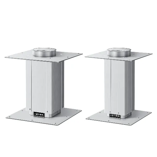
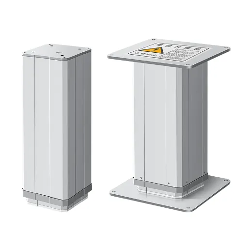
That is exactly the conversation we run at Hoodland. We build electric actuators and lifting columns with speed tiers specified as pairs: you pick the target speed and the load it must carry, and we match the motor, gearbox, and screw around them, with the duty rating and noise figure stated on the datasheet. No quantity minimum: a single unit is a legitimate order, and standard customization ships in 3–7 days, with more complex drive changes inside 15. If you are sizing an actuator for speed in production, talk through your speed spec with us, or start from our custom speed specifications page, and bring the four numbers.
The takeaway: making a linear actuator faster is not hard. The methods fit in a table. The hard part is what each method costs, and the honest way to get speed is to specify it as a system rather than bolt it on. Speed is never free; make sure someone is paying the bill on purpose.
Specify Your Speed, Get the Pairing Engineered
Target speed, load at that speed, duty, and noise ceiling: four numbers in, a matched motor-gearbox-screw set out. No minimum order: a single unit is a legitimate build.
Talk Through Your Speed Spec
 English
  Chinese