
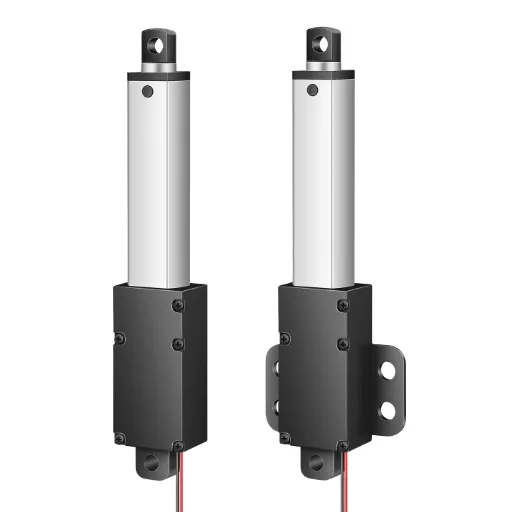
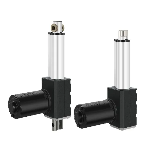
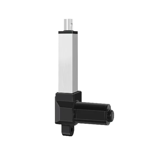
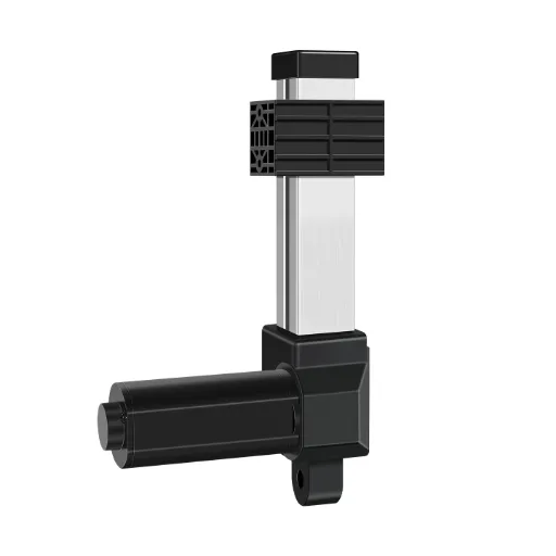
Stroke length is the first number most people fill in on an actuator datasheet, and the one they rework most often. It is not the total length of the unit, not the distance you see it move in your head, and not a number you can safely round to the nearest standard size without checking what the rest of your mechanism does. Get it right and the actuator disappears into your machine. Get it wrong and you are redesigning brackets, housing, or the whole linkage. This guide walks through what stroke length actually means, how to size it, and the hidden costs it drags into your design.
What Is Stroke Length on a Linear Actuator?
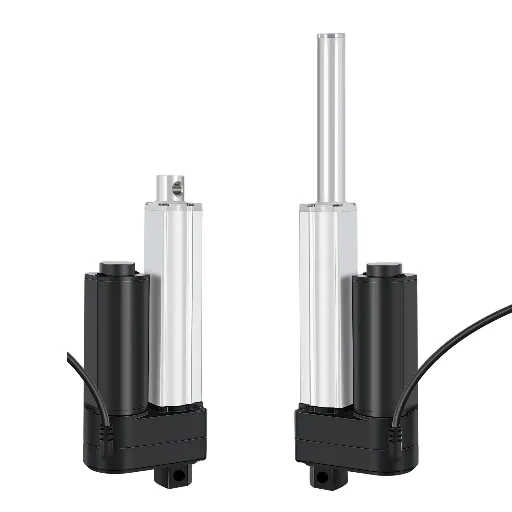
Stroke length is the net travel distance of the rod: the difference between the fully extended and fully retracted positions. In most datasheets it is the single number that defines how far the actuator can move a load, and nothing else.
Stroke length = fully extended length − fully retracted length
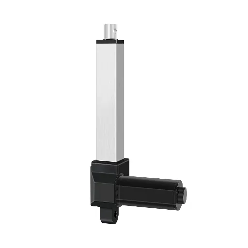
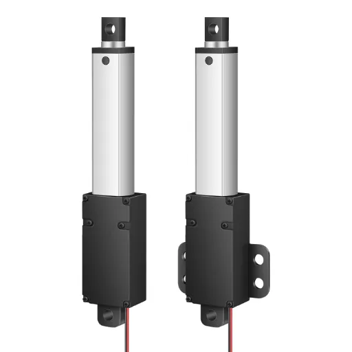
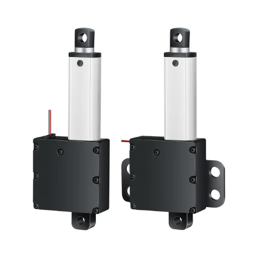
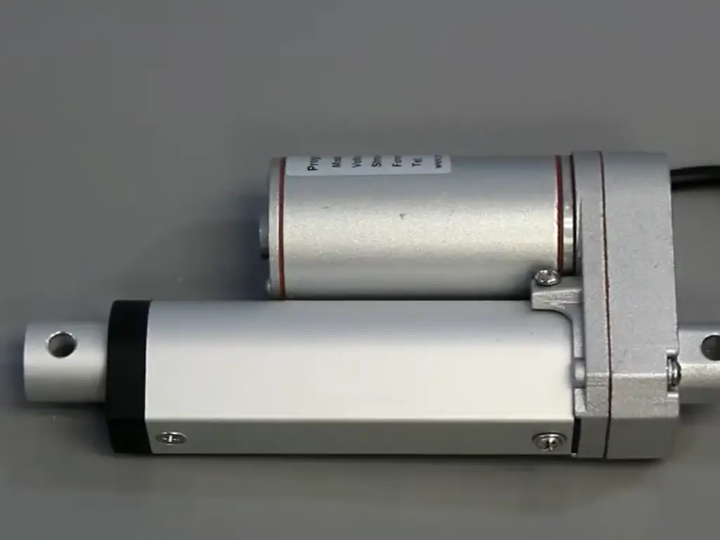
Two clarifications matter before we go further. First, the term “stroke length” is used in other industries for different things: pneumatic cylinder stroke is calculated from bore volume, and engine crank stroke is a crankshaft dimension. Search results for “stroke length” will mix those in; this article is only about electric linear actuators. Second, stroke is not the overall length of the unit. A 300 mm stroke actuator typically measures 450–600 mm when fully retracted, because the motor, gearbox, lead screw and limit switches all live inside the housing behind the rod. That gap between stroke and total length is where most installation surprises come from, and we will come back to it.
Standard strokes cluster into familiar ranges: short (25–100 mm) for compact flaps and vents, medium (100–300 mm) for doors, hatches and adjustable furniture, long (300–600 mm) for lifts and positioning, and extra-long (600 mm and up, to 2,000 mm in industrial models) for large-scale equipment. Knowing which band you are in is useful, but it is the geometry of your mechanism that decides the number.
How to Calculate the Stroke Length Your Application Needs
The calculation itself takes three measurements, and the discipline is in how you take them.
- Measure the closed position. With the mechanism fully retracted, measure between the two mounting points.
- Measure the open position. With the mechanism fully open, measure the same two points again.
- Subtract. Required stroke = open − closed. That is your minimum.
Take both measurements twice, ideally with two different methods (a string along the true hole-to-hole path, then a rigid template). If the numbers disagree by more than a few millimeters, re-measure. This is the cheapest error to fix.
Then apply two corrections that account for most real-world mistakes:
- Angled mounting. If the actuator pushes at an angle θ to the direction of travel, effective motion = stroke × sin θ. Mounted at 45°, you lose 30% of your stroke to geometry: a 300 mm actuator delivers only about 210 mm of useful vertical travel.
- Safety margin. Add 5–10% on top of the calculated minimum to absorb manufacturing tolerances (±3 mm is common), thermal expansion of linkages, and slight settling of brackets over the first months of use.
The result is your required stroke. What you do with that number (round up to the nearest standard size, or order the exact length) is a decision with real cost attached, and it deserves its own section later in this guide.
Stroke Sizing Checklist
- Closed position measured twice, two methods
- Open position measured twice, two methods
- Required stroke = open − closed
- Angled mounting correction applied (stroke × sin θ)
- Safety margin 5–10% added
- Retracted AND extended end-to-end lengths verified against available space
What Stroke Length Does to Your Design: Size, Load, and Speed Trade-offs
A stroke length is not just a travel number. Once you fix it, it drags three kinds of consequences into your design. This is the part of selection that most guides skim over, and the part that comes back to bite during installation.
The hidden cost: retracted and extended length
The actuator body does not shrink to fit your stroke. Retracted length is approximately stroke + structural allowance: the fixed length of motor, gearbox, lead screw, and end mountings. In one documented example, a 4-inch stroke actuator measures about 8.5 inches between mounting holes when retracted, and about 12.5 inches when extended (Progressive Automations, PA-09 datasheet example). The pattern holds across brands: extended length ≈ retracted length + stroke.
This is why “I need 300 mm of travel” is only half the spec. The other half is “do I have 450–600 mm of free space when the actuator is closed?” If you do not, a longer-stroke actuator will not fit no matter how much travel it offers, and you will be looking at a telescopic unit or a different mechanism entirely (covered in the next section). Before ordering anything, get the hole-to-hole dimensions at both extremes from the supplier and check them against your envelope.
The stroke-to-length math
extended ≈ retracted + stroke
Load, speed, and the cantilever effect
The further a rod extends, the more it behaves like a cantilever beam. Bending moment grows with M = F × L: at a given side load, a 600 mm stroke rod takes roughly double the bending moment of a 300 mm rod. Side loading, vibration and deflection risk all climb with stroke, which is why long-stroke units often use thicker rods, external guides, or derated load figures.
Two speed questions get confused constantly:
- Does stroke change rated speed? Within one model line, no; the rating is mm/s, and stroke does not alter it. But long-stroke variants are frequently built with different gear ratios to keep the motor in a safe range, so the actual speed of a long-stroke version may be lower than the short-stroke version of the same family. Check the datasheet rather than assuming.
- What matters in practice is total travel time. Travel time = stroke ÷ speed. At 30 mm/s, a 600 mm stroke takes 20 seconds end to end; a 300 mm stroke takes 10. If your cycle time budget includes this travel, it is the stroke, not the speed rating, that determines the delay.
Precision has a similar logic: a 1 mm positioning error is 1% of a 100 mm stroke but only 0.25% of a 400 mm stroke. Long strokes forgive positioning errors proportionally, but they punish mechanical play more, because the same angular play at the mount translates to more rod-end deviation.
Synchronization. If your application drives two actuators in parallel (a lifting table, a tilting platform), both must extend at the same rate. DC motors carry a typical speed tolerance of ±10%, so two nominally identical units will drift apart stroke-by-stroke without feedback. Hall-effect sensors feeding a controller are the standard fix; without them, a synchronized axis is a gamble on motor tolerance.
| Stroke range | Retracted length | Cantilever/side-load risk | Speed character | Failure point |
|---|---|---|---|---|
| Short 25–100mm | compact, fits tight housings | low risk | fast travel | none if sized right |
| Medium 100–300mm | stroke + 150–250mm allowance typical | moderate | standard | collision if clearance ignored |
| Long 300–600mm | needs real free space closed AND open | rising bending moment with side load | slower variants via gear ratio | rod flex under side load |
| Extra-long 600mm+ | body dominates layout | high, guides recommended | longer travel time | overextension into structure |
When the Stroke Doesn’t Fit: Rod, Track, Telescopic, and Scissor Alternatives
If your required stroke does not fit (too long for the space, or too short for the mechanism), the answer is usually not “bigger actuator.” It is a different way of realizing the motion.
Rod-style direct drive
The default: a rod extends from a fixed body. Simple, strong, cheap, and it has the worst length-to-stroke ratio: the body is always there, fully extended and fully retracted. Use it when space is not the constraint.
Track actuators
The body length stays constant while a carriage slides along a fixed rail, so the unit does not grow when it travels. Useful when extension space is limited and the load can ride on the carriage. The trade-off: an open architecture that is more sensitive to dust and water, which keeps track actuators mostly indoors.
Telescopic and multi-stage (lifting column)
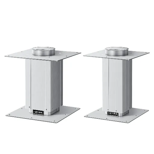
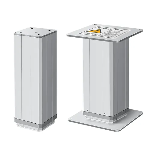
Nested stages extend from within one another, so a long stroke collapses into a short retracted package: a 600 mm stroke column can close to roughly half that. This is the standard answer to the classic engineering problem of “long travel in a short footprint,” and it is why lifting columns exist at all (typical column strokes: 50–1,000 mm). The cost is greater mechanical complexity and a higher price than an equivalent rod unit.
Long stroke, short envelope? Send us your travel and closed-length constraints and we’ll recommend the right mechanism.
Send my constraintsMechanism solutions: scissor, lever, and guide rails
When the stroke you need is out of reach entirely, change the mechanism instead of the actuator. A scissor or lever arrangement multiplies actuator travel into much larger platform movement; industrial scissor lifts have done this for decades, and patents for linkage-based lifting mechanisms are public history. If the problem is the opposite (the stroke fits but the rod flexes), add guide rails or linear bearings to carry side loads instead of downgrading your stroke to protect the rod.
One piece of spec language to master if you buy for industrial equipment: suppliers distinguish maximum stroke (the full mechanical range), working stroke (the travel your application actually uses), and safety stroke (working stroke plus buffer at each end so the carriage never slams into the physical stops). A sensible safety stroke is working stroke plus roughly four times the linear travel per motor revolution. A fast axis with a 3:1 gear ratio needs a much longer safety stroke than a slow 25:1 axis. Specify in working stroke and let the safety buffer be explicit, and you will avoid the most common miscommunication with suppliers.
| Option | Stroke-to-retracted ratio | Best for | Boundary |
|---|---|---|---|
| Rod-style | 1:1 + body length | simple applications with space | fails when space is tight |
| Track | body constant | limited extension space, guided loads | indoor only (dust/water sensitive) |
| Telescopic/lifting column | up to 2:1 | long travel + short footprint (50–1,000mm) | higher cost, more complexity |
| Scissor/lever + guides | multiply travel or carry side load | extreme travel or cantilever problems | adds mechanism cost, amplifies side loads |
Standard, Custom, or Limited Travel: How to Get the Exact Stroke Length
You have your required stroke (say, 950 mm), and the catalog offers 900 and 1,000. Three ways forward, and they are not equal:
- Round to the nearest standard. Fastest, cheapest per unit, and the most common cause of silent design debt: a 50 mm shortfall gets absorbed by the bracket geometry, the hinge position, or the frame, often without anyone noticing until first assembly.
- Limit the travel electronically. Limit switches, programmable stops, or feedback-based control can restrict how much of the stroke is used. They cannot add travel: “adjusting the stroke” in software only ever shortens it. Use limits when you have spare stroke and want to protect the mechanism, not when the stroke is short.
- Order the exact stroke. This is where supplier capability diverges, and the difference matters more than most buyers realize.
Here is the part that gets buried in vendor content: custom stroke is routine for some OEMs and nearly impossible for others, and the pricing story is the opposite of what you would expect. A well-known North American brand states outright in its FAQ that custom strokes “typically involve higher costs and longer lead times” and that selecting the next standard size is usually “more practical and economical” (Firgelli Automations, FAQ). Meanwhile, other manufacturers (typically Chinese OEMs with in-house mold, injection molding and CNC capacity) quote custom strokes as standard service: no minimum order quantity, a single unit accepted, free prototyping on request, and 3–7 days for standard custom builds (up to about 15 days for complex changes like a different motor).
Custom stroke, standard service
- 1Can you make a non-standard stroke length, and is there a minimum order quantity?
- 2Who does the prototype (do you have in-house mold and CNC, or is it outsourced)?
- 3What is the lead time for a standard custom stroke, and for a complex one?
When the difference between “rounding up” and “exact fit” is a bracket redesign on every unit you ship, the custom route stops being a premium and becomes the economical one. The deciding factor is not price; it is whether your supplier can actually do it.
Stroke Selection Mistakes That Cost You a Redesign
- Too short. Incomplete motion, mechanisms that bind before reaching their end position, and, in the worst case, a system redesign. This is the most expensive error because it is discovered last.
- Too long. Overextension into surrounding structure, mechanical collisions, wasted space and cost. A longer stroke also raises the cantilever risk described earlier, which can shorten service life even when the travel itself is fine.
- Ignoring mounting geometry. Measuring the visible distance but forgetting the brackets, the hinge offset, or the 30° mount angle. The 5–10% margin is there precisely for this; skip it and tolerances eat your design.
- Ignoring tolerance and temperature. ±3 mm build tolerance on the actuator, plus thermal expansion of the mechanism between winter and summer, quietly absorbs a “just fits” stroke, until it doesn’t.
- Skipping the test. Before production, move the mechanism by hand (if it binds by hand, power will hide it), then run at least 20 real-load cycles including failure drills: blocked motion, power loss, limit switch fault. A prototype that works once proves an idea; twenty cycles with the real load proves the design.
The Business Case for Getting Stroke Right
None of this is academic once it reaches procurement. Consider the actual cost structure of getting it wrong.
A stroke that misses by one standard step forces a bracket or mechanism redesign. That redesign touches drawings, prototypes, validation, and the schedule of whatever machine the actuator is going into. A project delay of even a few days typically costs more than the price difference between a standard and a custom-stroke actuator, which is why the “custom is premium” assumption is exactly backwards when you price the consequences instead of the part.
The market context supports treating stroke engineering as a normal service rather than a rarity. The global electric actuator market was estimated at roughly US$2.55 billion in 2022 and is forecast to reach about US$3.30 billion by 2029 (QYResearch, as reported by Yahoo Finance): a growing base of buyers, most of whom will discover the same sizing lessons this article covers. The long-term direction is unmistakable: customization and application-specific engineering, not catalog standardization, is where the value is.
For procurement, that translates into three lines on the supplier evaluation sheet: custom stroke availability, minimum order quantity, and prototype lead time. These three questions do more screening work than any brochure. Custom capability implies in-house mold, injection molding and CNC: the physical infrastructure that lets a supplier prototype a non-standard stroke in days instead of weeks. Ask who does the prototyping, and you can sort an engineering manufacturer from a trading house in one call.
Hoodland builds linear actuators the way we just described. Our line spans 25–2,000 mm of stroke, and we accept orders of a single unit with no minimum quantity. Non-standard strokes are prototyped in-house, in our own mold, injection molding and CNC departments. Standard custom builds leave in 3–7 days; complex custom work (a different motor, for example) takes about 15 days. If you are sizing a mechanism now, our custom stroke engineering page walks through what we can change, or you can send us your mounting and stroke requirements and we will work through the geometry with you.
So the decision rule is simple: size the stroke from your mechanism’s true motion, price the consequence of rounding, and treat custom stroke as an evaluation criterion rather than a premium. The suppliers who can deliver it are the ones worth the conversation. If you are mid-spec right now, send Hoodland your stroke and mounting requirements and get a prototype decision back in days, with no order size required.
Get Your Custom Stroke Spec’d in Days
No minimum order, free prototyping, standard custom builds in 3–7 days — send us your stroke and mounting requirements.
Start with your dimensionsReferences
- QYResearch. “Global Electric Actuator Market Growth Accelerates Amid Automation Demand.” 2025. finance.yahoo.com
- Progressive Automations. “Linear Actuator Stroke Length Guide | How to Choose Correctly.” progressiveautomations.com
- Firgelli Automations. “Can You Adjust Linear Actuator Stroke Length? Options, Limits, and Safer Alternatives.” 2026. firgelliauto.com
- Firgelli Automations. “What is the Stroke of a Linear Actuator?” firgelliauto.com
- Rollon. “Difference Between Stroke, Working Stroke, and Safety Stroke.” rollon.com
- Hoodland. “Custom Solutions.” thehoodland.com/custom-solution
- Hoodland. “Contact Us.” thehoodland.com/contact-us
- Hoodland. “Linear Motion Solutions: Home.” thehoodland.com
 English
  Chinese