
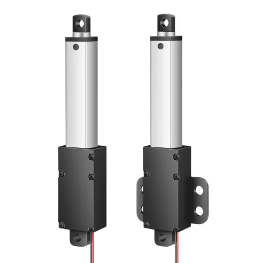
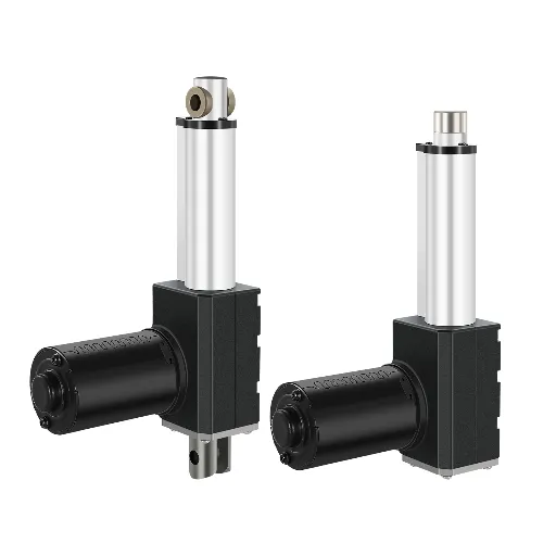
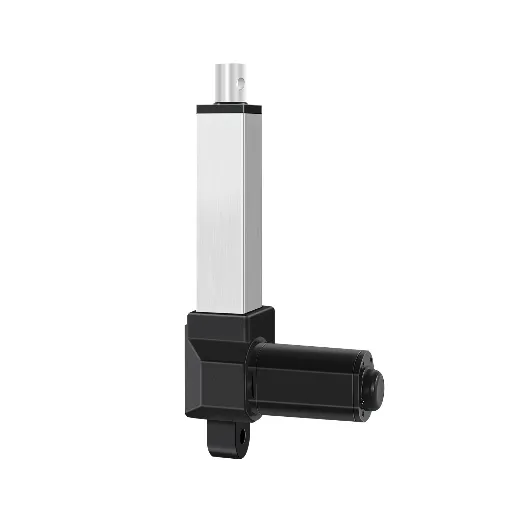
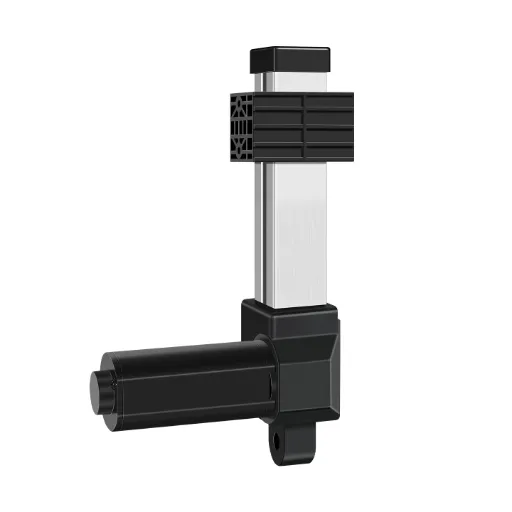
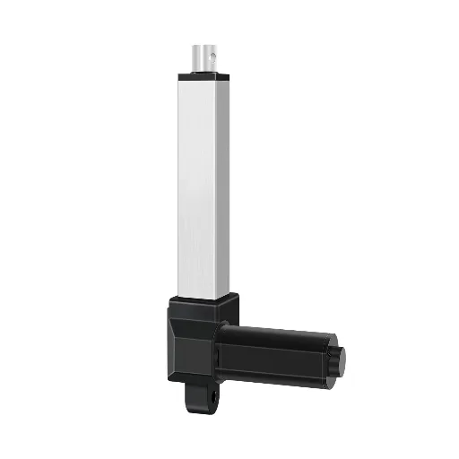
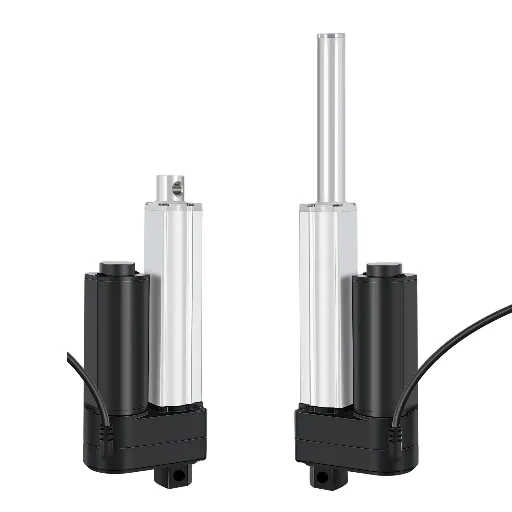
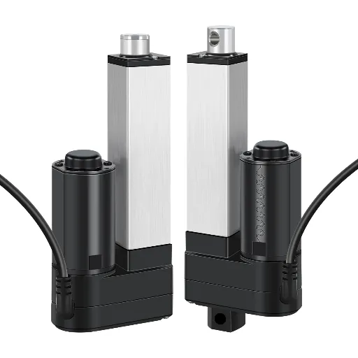
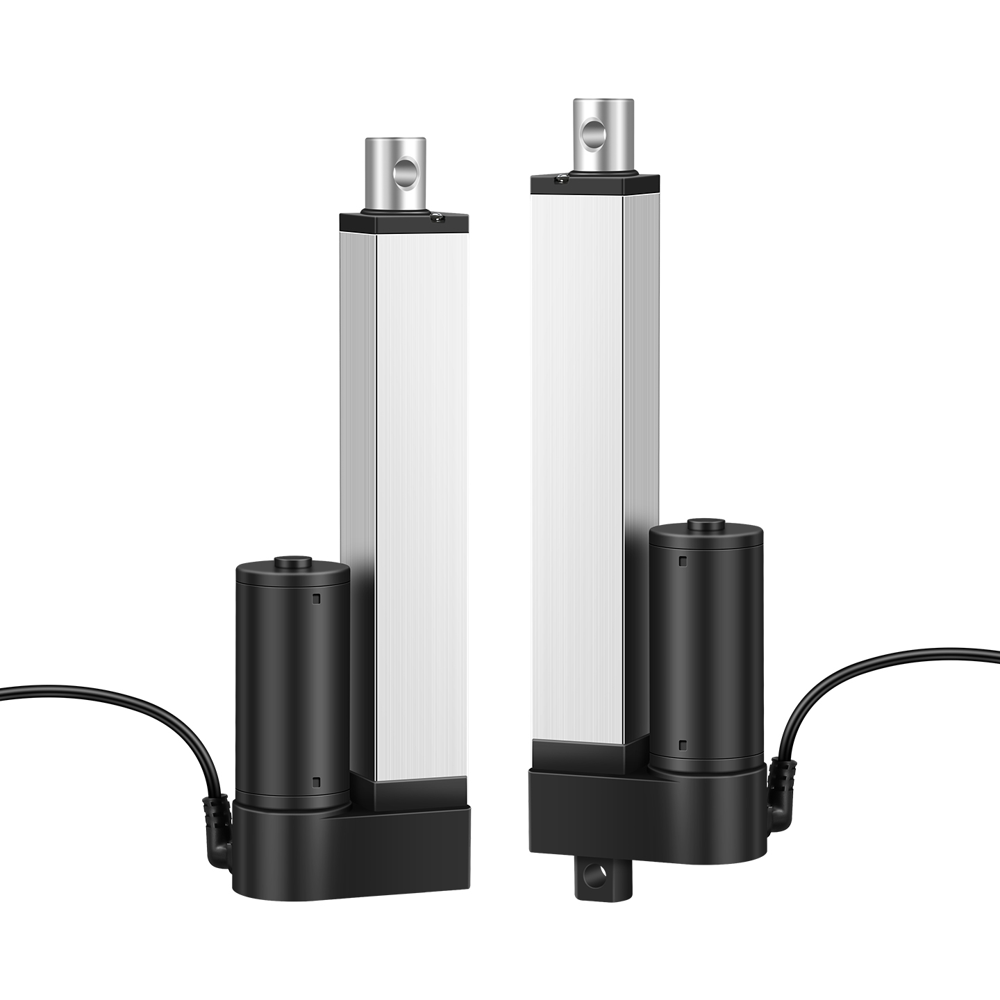
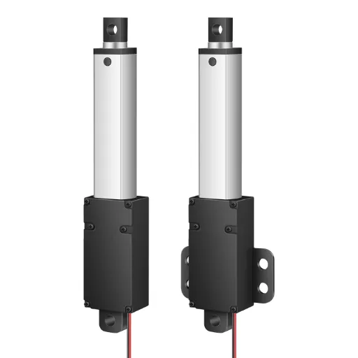
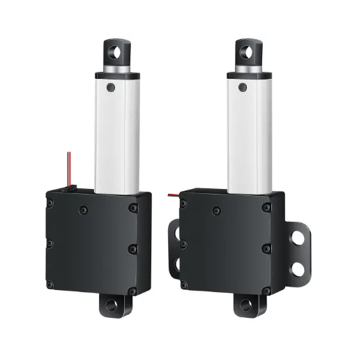
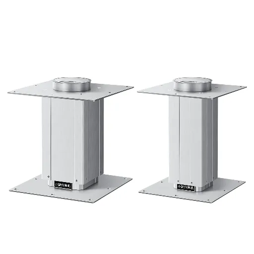
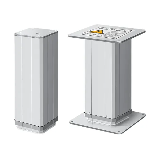
Every electric linear actuator works on the same physics: a DC motor turns a lead screw, and the screw pushes a rod in and out. The control system around that rod is where projects get built — and where they get stuck. Here is what you actually need, from a two-wire setup you can wire in ten minutes to a closed-loop system that holds position to a fraction of a millimeter.
What Actually Needs to Be Controlled: Power, Direction and Limits
First, a scope note: “actuator” also appears in pneumatic and hydraulic contexts. Pneumatic cylinders need an air supply and valve stack; hydraulic units need a pump and directional valves. This guide covers electric linear actuators — the DC-motor-plus-lead-screw kind used in everything from standing desks to factory automation — where the entire control problem reduces to three things: power, direction, and limits.
Direction is the whole secret. A DC linear actuator is a two-wire device. Apply 12 V one way and the rod extends; reverse the polarity and it retracts. Every control method in this article — switch, relay, H-bridge, controller, PLC — exists to do one job: swap those two wires in a controlled way.
The minimum viable system is therefore three components:
- A power supply matched to the actuator’s rated voltage — 12 V and 24 V DC cover the vast majority of units.
- A DPDT (double-pole, double-throw) switch to reverse polarity by hand. As Thomson Linear puts it, “many DC and AC actuators can operate from a power supply and a Double Pole, Double Throw (DPDT) switch” (Thomson Linear, n.d.).
- Built-in limit switches at the ends of stroke, which cut power automatically at full extension and retraction — standard on most DC actuators, and the reason a bare actuator won’t self-destruct when it reaches the end of travel.
The minimum system, in four steps
This minimum system is complete — and it is also strictly limited. It stops only at the two mechanical ends, never in between. It has no speed control, no feedback, and it needs a human in the loop. If your application needs anything more, the next level adds the first real component: automated direction control.
Direction, Limits and Power: The Three Components
Once a human operator is no longer the reliability plan, you start buying components. Three categories matter, in this order.
Reversing Direction Automatically: Relays, H-Bridges and Contactors
The DPDT switch’s job is done by two relays: one drives the rod out, one drives it in. The coils are switched by your control signal; the contacts carry the actuator current. This is the point where a common confusion needs clearing up — you’ll read “a minimum of 2 relays” on one forum, “a DPDT switch is enough” from one manufacturer, and “two relays are essential” from another. All three are the same physical fact: a two-wire DC actuator needs a polarity swap, and a switch, a relay pair, or an H-bridge are interchangeable expressions of it. Which you pick is a current question, not a physics one.
- Switch or relay rated above the actuator’s peak (stall) current — check the spec sheet; the stall figure is what kills underrated components, not the rated load current.
- H-bridge if you want speed control later — PWM needs a driver, not a relay.
- A contactor only enters when you’re switching tens of amps, which means a large industrial actuator.
Limits: Built-in, External or Soft
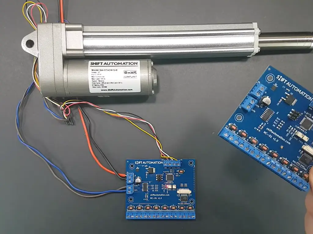
Built-in limits are the reason a bare actuator is safe to power up out of the box. External limits are how you stop it anywhere else. Soft limits are how you stop it anywhere — but they demand feedback, which is the subject of station five. If you are asking “how do I set limits,” the answer is a cascade: built-in for the ends, external micro-switches for custom positions, soft limits when you already have feedback. Trying to make one approach do the other’s job is where wiring gets fried — the “limit switches or not” confusion that shows up constantly in beginner threads is almost always a built-in/external mix-up (r/arduino, 2025).
| Approach | Where it lives | When it’s enough | When it fails |
|---|---|---|---|
| Built-in (mechanical or electronic) | Inside the actuator housing, trips at full extension/retraction | Enough for two-position travel; zero extra wiring | Covers only the two ends; never a mid-stroke stop |
| External micro-switch | Wired by you at any point along the stroke | Custom stop positions; trip the control circuit directly | Needs mechanical mounting and careful wiring; a mis-wired limit can short the switch (a classic first-project failure) |
| Soft limit in the controller | In firmware, based on feedback | Any position, including mid-stroke; no extra hardware | Requires position feedback and a controller; useless on a bare two-wire actuator |
Power: Voltage, Current and Duty Cycle
Voltage must match the actuator rating exactly. Current is a budget: add the actuator’s stall current to anything else on the same supply, then size the wire and fuse for the sum. Duty cycle is the parameter nobody budgets for until something melts. Standard electric linear actuators are rated for duty cycles between 10% and 25% — meaning 1–2.5 minutes of running per 10-minute window, with the rest spent cooling (Firgelli Automations, 2026). Push past it and the motor windings overheat — insulation degrades, and a 10°C rise above rated temperature roughly halves insulation life (per the Arrhenius thermal aging model, IEEE 117). A 25%-duty actuator asked to run continuously will die, not slowly degrade: it will run slower, then draw more current, then stop.
A first-project classic: two relays, one direction wired backward, no fuse on the supply. Result — a burned relay and a dead actuator. Before you power anything: verify the wiring diagram against the relay datasheet, and fuse the supply at 1.5x the actuator’s rated load current.
Programmed Control: Microcontrollers and Control Boxes
Once you want buttons, remotes, memory positions, or synchronized multi-actuator motion, you move from circuit to program. Two roads lead there.
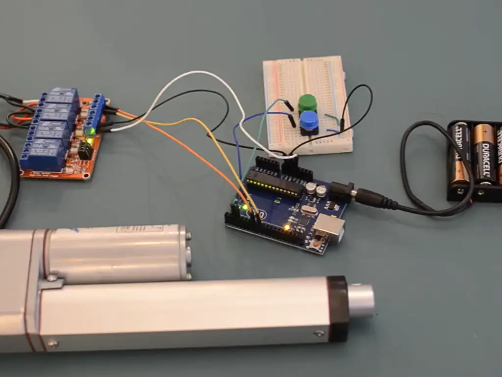
Roll your own: a microcontroller (Arduino-class or Raspberry Pi) driving a relay board or motor driver, with PWM for speed. This is the most documented path on the internet, it teaches the most, and it is the right choice when the project is one unit and your time is cheap. The boundary is honest: PWM throttles voltage, and at low speeds a DC motor’s torque falls off — a slow actuator under load may simply stall.
Buy a control box: a packaged unit with transformer, relays, handset or remote, and often memory positions and sync channels, made to bolt onto a 12/24 V actuator. Control boxes are how commercially shipped products (furniture, lifts, adjustable workstations) are actually built. When you specify one, the parameters that matter are: input voltage (110/220 VAC in, 12/24 VDC out, or DC direct), channel count (one per actuator), and whether it accepts your actuator’s feedback if you need memory positions.
One sentence on the trade-off: build your own when the function list is short and the volume is one; buy a box when it has to work reliably in a product that ships.
Unsure which control level your project needs?
Send the stroke, load and duty cycle — we’ll flag what the actuator has to carry on board.
Which Control Level Do You Actually Need?
By now you’ve seen the five levels — switch, relay circuit, control box, microcontroller, PLC. The question is which one your project earns, and the honest answer comes from one question: where does the rod need to stop?
| Control level | What you add | Right when | Reconsider when |
|---|---|---|---|
| Manual DPDT switch | Power supply + switch | Two-position travel, human always present | Any automatic timing, any mid-stroke stop |
| Relay circuit | 2 relays + limits + fused supply | Automated two-position travel, low volume | Precision positions, high cycle rates |
| Control box | Packaged relays + remote/memory/sync | Consumer & commercial products (furniture, medical, home) | You need industrial protocols or IO |
| Microcontroller | Board + driver + code | One-off prototypes, learning, IoT-style control | You need certification, support, or scale |
| PLC + feedback | Digital IO / analog module + position sensing | Production equipment, repeatable positioning, machine safety | Single-unit hobby projects |
Worked examples: a TV lift moves to two ends a few times a day — the switch or relay level is already overspecified. A motorized door that must stop at a position set by a sensor needs a controller with feedback, because neither limit switch approach covers mid-stroke. An assembly cell that positions a fixture to ±0.5 mm every cycle, powered up and down every shift, is a closed-loop question from day one — and that’s the level where actuators start needing feedback options built in at the factory, not bolted on later.
This is not a shrinking problem. The global linear actuator market was valued at USD 67.11 billion in 2025 and is projected to reach USD 91.36 billion by 2030, a 6.37% CAGR (Mordor Intelligence, 2025). More actuators are going into more machines, which means more control systems being specified, and more engineers making this exact decision.
Global linear actuator market
USD 67.11B
2025 market value
USD 91.36B
Projected by 2030
6.37%
CAGR
Source: Mordor Intelligence, 2025
Feedback and Closed-Loop: When Simple Switches Stop Being Enough
Here is where actuator control stops being a wiring exercise and becomes an engineering discipline. The moment your rod must stop at an arbitrary position — and especially the moment it must return to that position after power loss — switches cannot help you. You need to know where the rod is.
The Feedback Spectrum
The spectrum has a logic: relative sensors (hall, incremental encoder) tell you how far you’ve moved, so they can’t tell you where you are after a power cut. Absolute position — required if your machine must resume after an outage — means an absolute encoder, or a homing routine. The most expensive option (LVDT) is the least-used for a reason: in most applications it’s precision you pay for and never need.
| Option | Signal | Precision tier | Cost tier | Failure mode |
|---|---|---|---|---|
| Potentiometer | Analog (e.g. 0–10 V), position-proportional | Coarse, cheap | Low | Wears with travel |
| Hall-effect sensor | Digital pulses (quadrature: count + direction) | Medium | Low | Contactless, but pulses are relative — lose position on power loss |
| Incremental encoder | Pulse count | High | Medium | Needs homing after power-up |
| Absolute encoder | Digital absolute position | High | High | Holds position across power loss |
| LVDT | Analog, non-contact | Highest | Highest | Overkill for most applications |
Homing and Power-Loss Recovery: The Failure Nobody Plans For
Here is the case that should change how you spec a project. A manufacturer built mechanical fixturing first, brought in a controls engineer afterward, and discovered the actuator had to home to a middle position on power-up — with a fixture at risk of roughly USD 10,000 in damage if it didn’t (eng-tips forum, 2011). The thread’s verdict on mid-stroke homing with an incremental encoder: “halfway is a bitch.” The practical solutions — two complementary position switches, an absolute encoder, a cam-plus-switch reference routine, or a safety reset button — are all implementable, but they are architecture, not wiring. Every one of them was cheaper than the rework of retrofitting control after the mechanics were fixed.
The most expensive mistake in this article
If the control architecture is decided after the mechanical design is frozen, the rework cost is paid in machine downtime, not in components.
Power-loss recovery is a spec item, not an afterthought. Ask it on day one: “Where is the rod when power comes back, and does the machine know?” If the answer requires a homing routine or an absolute encoder, that capability must exist in the actuator and controller you buy — it cannot be added reliably later.
Talking to a PLC — and What the Actuator Owes You
Industrial integration is simpler than it looks. The most-recommended reliable low-cost pattern — repeated on r/PLC whenever this comes up — is a plain actuator with position switches driven from discrete PLC outputs: “dumb actuator + position switches,” no feedback, no programming beyond the ladder logic (r/PLC, 2023). It works because discrete IO is the industrial lingua franca. Add an analog module and a potentiometer feedback actuator, and you get continuous position. Add RS-485 or CAN, and you’re in bus-control territory with actuators that were built for it from the start — smart actuators don’t accept retrofits.
The higher the control level, the more the actuator itself must deliver: repeatability and a duty cycle with margin (a common engineering practice is to derate 1.5–2x on duty cycle (Firgelli, 2026)), built-in limits that actually trip, and feedback options available at the factory — not promised after the PO. This is also where lifespan claims stop being marketing: a 30,000-cycle rating, verified by a 2-hour aging test on every unit, is the kind of number you should demand in writing (thehoodland.com, 2026).
The Business View: Make Control Part of the Spec
Every fact in this article points one direction: the control level decides what the actuator must carry on board, and that decision is cheapest on the day you write the inquiry — not the day the machine goes into production. When you ask a supplier for a quote, the control question should be on the same line as the stroke and force, because a supplier who can’t answer it will send you to the engineering department later. That later conversation is exactly where rework costs come from.
A practical checklist to run against any quote:
The inquiry checklist
This is not an engineering luxury for big projects. It’s the difference between buying an actuator and buying a solved problem. In a market growing at 6.37% a year (Mordor Intelligence, 2025), suppliers who can solve the control problem are increasingly the ones worth talking to at all.
If you’re evaluating actuators for a controlled application, Hoodland offers linear actuators with custom feedback, limit and wiring options — down to single-unit orders — built in-house at their factory (custom-solution).
Bring us your control architecture
Custom feedback, limits and wiring — from a single unit to full batches — quoted together with stroke and force.
Send your control requirementsReferences
- Firgelli Automations. “Linear Actuator Duty Cycle: What It Is & Why It Matters.” 2026. https://www.firgelliauto.com/blogs/actuators/what-is-a-linear-actuator-duty-cycle-and-why-does-it-matter
- Mordor Intelligence. “Linear Actuators Market Size, Share & 2030 Growth Trends.” 2025. https://www.mordorintelligence.com/industry-reports/linear-actuators-market
- eng-tips. “Need to home to a middle position.” 2011. https://www.eng-tips.com/threads/need-to-home-to-a-middle-position.294802/
- Reddit r/PLC. “Linear actuator control ideas.” 2023. https://www.reddit.com/r/PLC/comments/11orta0/linear_actuator_control_ideas/
- Reddit r/arduino. “Struggling to control linear actuator! Limit switches or not?” 2025. https://www.reddit.com/r/arduino/comments/1g32evl/struggling_to_control_linear_actuator_limit/
- Thomson Linear. “What is needed to control a linear actuator?” n.d. https://www.thomsonlinear.com/en/support/tips/what-is-needed-to-control-a-linear-actuator
- Hoodland. “Custom Solution.” n.d. https://www.thehoodland.com/custom-solution/
- Hoodland. “Homepage.” 2026. https://www.thehoodland.com/
 English
  Chinese