
Linear Actuator Parts Diagram: Reading the Drive Chain
Open any electric linear actuator and you will find the same story told in metal and plastic: a rotary motor, a gearbox, a threaded screw, and a nut that turns rotation into straight-line motion. Once you can read that drive chain, every “linear actuator parts diagram” you meet — from a hobbyist teardown to a manufacturer’s parts list — becomes the same picture with different labels.
This article walks the chain part by part, then goes a step further than the usual diagram: it tells you what each component really determines, what fails first, and how to use a parts list to judge an actuator you are about to buy. (We are talking about electric linear actuators here — pneumatic and hydraulic cylinders are a different parts system entirely.)
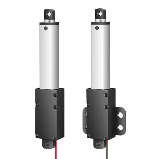
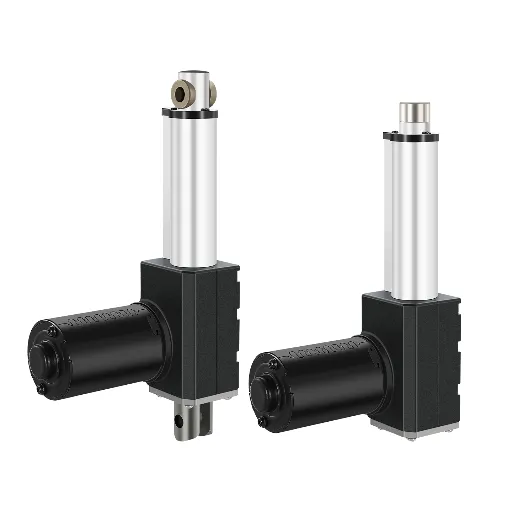
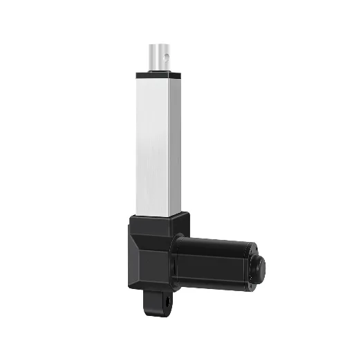
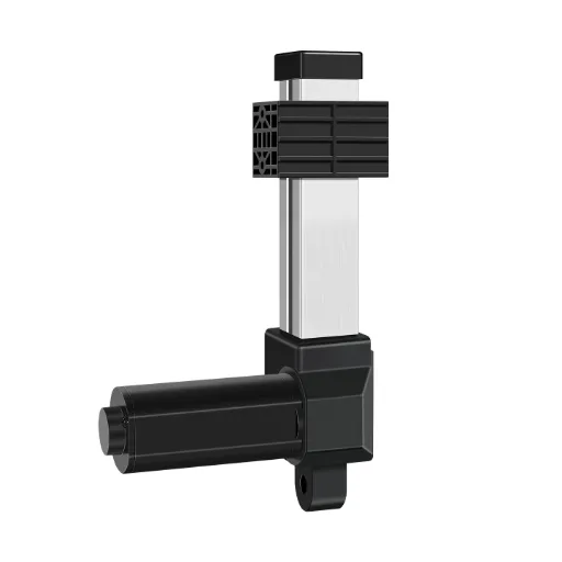
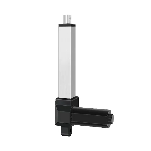
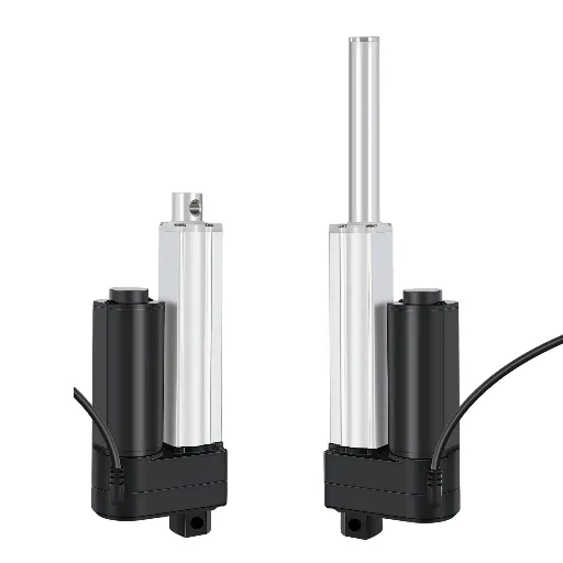
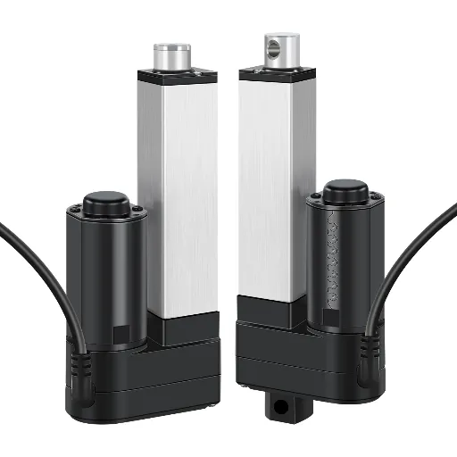
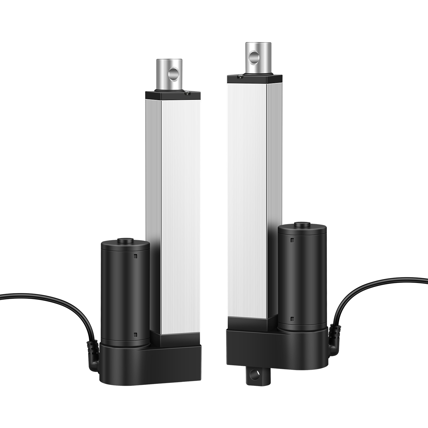
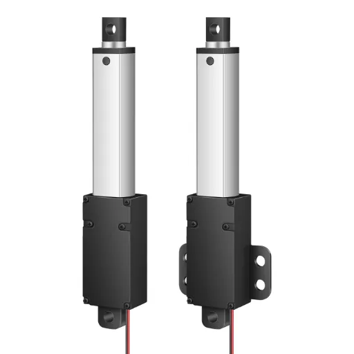
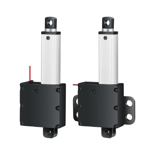
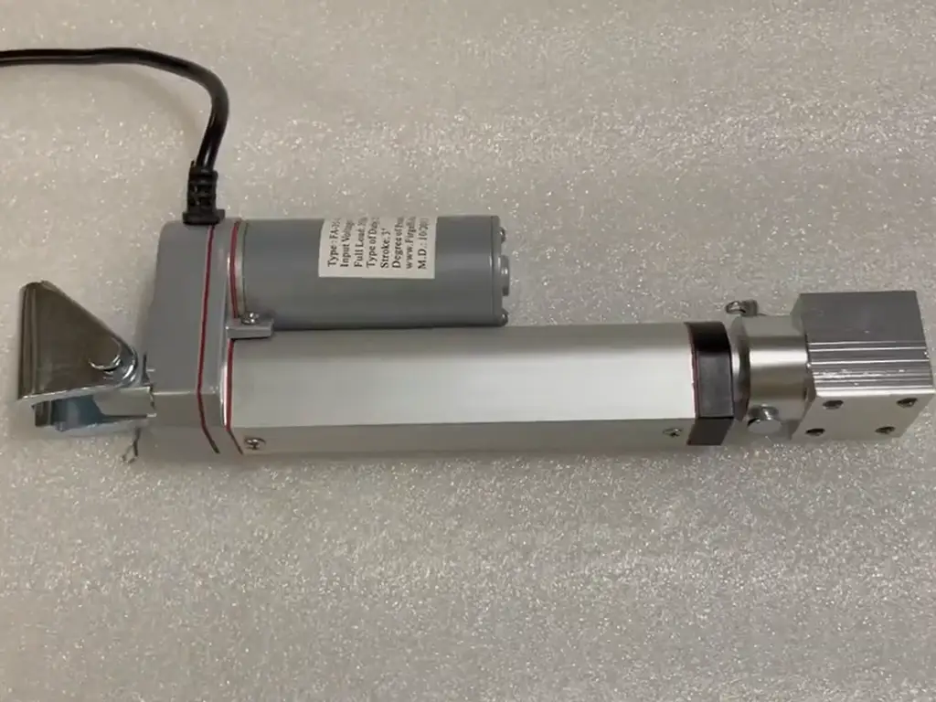
The chain runs in one direction. A DC motor spins a gearbox, which trades speed for torque. The gearbox drives a lead screw, which rotates without moving forward. Riding on the screw is a drive nut, fixed to the inner push tube; because the nut cannot rotate with the screw, it is forced to travel along the threads. The inner tube slides inside an outer guide tube, and the whole assembly pushes or pulls through two end fittings — usually clevises — that connect to your equipment. At both ends of travel, limit switches cut the power so the unit stops instead of over-extending.
| Part | What it does | Where you’ll find it |
|---|---|---|
| DC motor | Spins the whole chain; voltage 6–24V DC in most units | Rear housing |
| Gearbox | Cuts speed, multiplies torque; determines noise level | Between motor and screw |
| Lead screw | Converts rotation into thread travel; trapezoidal or ball type | Inside the tube |
| Drive nut | Rides the screw; the wear part that turns rotation into push | On the screw |
| Inner tube / push rod | Carries the load out of the unit | Extends from the outer tube |
| Outer tube | Guides and protects the moving parts | The visible body |
| Limit switches | Cut power at stroke ends | Built into the housing ends |
| Clevis / end fittings | Connect to your equipment; allow rotation | Both ends |
| Wiring | Delivers power; limit-switch and feedback lines | Exits the rear housing |
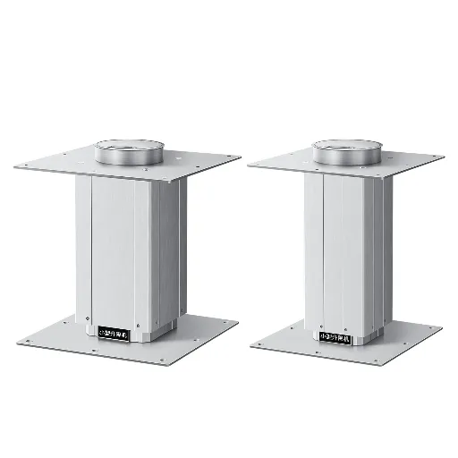
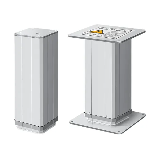
Three variations worth knowing before you compare diagrams: rod-style actuators (the tube slides over a fixed screw), track or slider actuators (a carriage rides a rail instead of a screw), and screw-driven vs. belt-driven designs. The parts names change, the drive-chain logic does not.
Two Construction Differences That Change the Parts You See
Two choices in the drawing explain most of the visual difference between actuators: the screw type and the motor type.
Screw type. Trapezoidal (acme) lead screws are the default: inexpensive, self-locking under load, and tolerant of dirt. Their trade-off is backlash, a little play between screw and nut, and efficiency around 50–70%. Ball screws replace the sliding contact with recirculating balls: efficiency jumps to 80–90%, backlash almost disappears, and positioning becomes precise. The costs: price, and no self-locking, so a vertical load can back-drive a ball screw and you need a brake or a worm-gear stage.
Motor type. Brushed DC motors dominate entry and mid-range actuators: simple, cheap, and the brushes are a wear item you should expect to replace eventually. Brushless motors last far longer but cost more. Stepper-driven actuators appear where open-loop positioning matters more than raw force.
A third detail — the gear stage — sits between them. Planetary, worm, and spur gears all do the same job with different noise and life profiles. You will see it matter in the next section.
The Gear Question: Why Metal Gears Are Not an Automatic Win
Here is the biggest surprise in the hobby and repair forums: “it has metal gears, so it must be better” is the assumption, and it is not true. The gear material is the first quality judgment an actuator earns, and metal does not automatically win.
What gears decide is everything you hear and everything you replace: noise and lifespan. In a drive chain that cycles tens of thousands of times, the gear teeth are the first component to wear out — stripped teeth, rising noise, then failure.
The counterintuitive finding from manufacturers’ comparison testing: non-metal gears made from engineering plastics (DuPont POM is the common choice) actually outlast metal gears in normal use — about twice the service life in documented comparison tests — while running below 50 dB. The reason is material compatibility: a hard metal tooth grinding a hard metal tooth wears and creaks; a POM tooth meshing against the same material absorbs and distributes contact stress, and it does not corrode. That is why medical-device and smart-home manufacturers — the buyers with the strictest noise limits — spec non-metal gears deliberately.
The gear numbers that matter
A fair boundary, in both directions: the plastic-gear advantage assumes normal duty. Continuous heavy loading, high ambient heat, or abuse beyond rated duty cycles will wear any gear, and for sustained high-torque industrial duty, reinforced or metal gearing is still the right call. When you read a parts diagram, the question is not “metal or plastic?” — it is “what material, tested how, and what does the noise and life data say?”
This is also where the industry is moving. Actuators are getting quieter and longer-lived across the board because the demanding buyers — medical, furniture, industrial automation — are pushing the same requirements: lower decibels and longer cycles. The 10,000-cycle baseline that was acceptable a decade ago is becoming the floor, not the target.
Parts × Quality: What Each Component Really Determines
Now the full judgment map. Each component below has a “good design” answer, a failure boundary, and a verification action you can take before you buy.
The Lead Screw and Drive Nut: Where Lifespan Lives
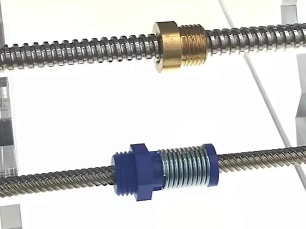
The screw and nut pair is the second-biggest wear center after the gears. A trapezoidal screw with a self-lubricating plastic nut is the mainstream industrial choice: the nut is designed to be the sacrificial part, it is cheap to replace, and the screw’s surface finish determines how long the nut survives. A rough or soft screw shortens nut life dramatically.
Choose by application: standard push-pull and furniture use → trapezoidal screw with a replaceable nut. Precision positioning, synchronized multi-actuator systems, or frequent mid-stroke stops → ball screw (accept the price and the no-self-lock caveat). Vertical loads with ball screws need a brake or worm stage — confirm it before you order.
Limit Switches vs. Feedback Sensors: A Control Fork in the Road
Look at the wiring in any parts diagram and you can tell what the actuator can do. Built-in mechanical limit switches mean the unit stops at both ends of stroke by itself — simple, reliable, and all most applications need. A wiring harness that carries sensor lines (Hall effect, potentiometer, or encoder) means the unit can report position and be controlled mid-stroke.
Take a concrete example: Hoodland’s IP60 actuator ships with limit switches built in as standard, a T-type lead screw, and a 10% duty cycle (2 minutes max continuous) — the kind of precise spec to demand from any supplier instead of a vague “industrial grade” (full parameters are on our datasheet). If you need synchronized desks, multi-point stops, or closed-loop control, budget for a feedback variant and a matching controller; if you only need extend/retract, paying for feedback is wasted spend. Note that potentiometer feedback is itself a wear part — it has a finite life like the nut does.
Limit switches only: stop at both ends. Hall/potentiometer/encoder feedback: position control anywhere in the stroke, needs a controller, costs more.
Seals, Tubes, and IP Ratings: Who Sets Your Application Boundary
The housing parts decide where an actuator is allowed to live. IP ratings are the language: IP44 keeps light splashes and dust out; IP65–IP66 seals against jets of water and heavy dust. The difference is mostly the seals, the wiper on the push tube, and how the housing is closed. Anodized aluminum tubes resist corrosion and keep the rod sliding smoothly.
Check the claim, not the sticker: ask what seals are used, whether the rating is tested, and whether the variant is rated for immersion or just weather. For energy-storage and hazardous environments, look for an explosion-proof variant — e.g., Ex ib IIA T6 Gb certification — which almost no Chinese actuator maker offers.
| Part | Good design looks like | Failure boundary | Verify before you buy |
|---|---|---|---|
| Gear set | Material and tooth profile documented; low noise; non-metal (POM) proven 2× life | Sustained heavy duty and overheat wear any gear | Ask material; ask for noise and cycle test data |
| Lead screw | Type matches application (trapezoidal self-lock vs ball screw precision) | Backlash growth; vertical load back-drive on ball screws | Ask type; check backlash |
| Drive nut | Self-lubricating; replaceable as a spare | Wear noise; looser travel | Ask material; confirm spare availability |
| Limit/feedback | Limit switches built in; sensor options match control needs | Stroke-end overrun; lost position | Confirm built-in limits; feedback type |
| Seals and tube | Real IP rating; anodized tube; tested seals | Water and dust ingress; corrosion | Ask for IP test evidence and materials |
| Duty rating | Stated duty cycle with max continuous time | Overheat and premature wear | Confirm duty cycle; e.g. 10% / 2 min max |
Which Part Failed? A Symptom-to-Part Diagnosis Map
When an actuator misbehaves, the symptom tells you which component to suspect — and this map works for hobby units and industrial ones alike.
Symptom to Component: The Failure Lookup Table
| Symptom | Most likely part | Secondary suspect | Quick check |
|---|---|---|---|
| No movement at all | Motor or wiring | Controller | Measure voltage at the motor under load |
| Noisy / grinding | Gear set wear | Dry lead screw | Run without load and localize the sound |
| Slow or weak | Voltage drop | Worn nut or gears | Loaded speed test vs. spec |
| Loose travel / slip | Drive nut wear | Screw backlash | Push-pull by hand and feel the play |
| Runs past the end | Limit switch failure | Controller | Bypass-test the limit switch |
| Water or rust inside | Seal failure | Corroded tube | Check IP rating and seal condition |
The failure stories behind this table are common enough to be a genre on repair forums: stripped gear sets on cheap units (often cheaper to replace than repair), corroded bearings and steel parts after submersion, and units run at full extension under max load until something gives. A pattern shows up in almost every account: the failure was a part design decision — gear material, seal quality, rated duty — made at purchase time, not a random event.
Repair or Replace: Where to Draw the Line
A practical rule of thumb: when the repair cost approaches half the price of a new unit, replace it. Wear items — the drive nut, brushes, seals — are worth replacing; structural damage — a bent screw, cracked housing, burnt motor — is not.
Two warnings. Second, in explosion-proof or safety-critical installations, do not field-repair; replace with the certified variant. When the diagnosis is uncertain, a proper bench test (voltage under load, sound localization, manual push-pull) costs an hour and saves a wrong order.
Don’t void the warranty
If the actuator is under warranty, contact the manufacturer before opening it — disassembly voids most warranties, and a warranty failure should cost you nothing.
How to Vet a Supplier by Its Parts List
By now you can read any parts diagram as a quality statement. Use it as a vetting checklist when you talk to suppliers:
The supplier parts-list vetting checklist
- Gear material — can they state it, and do they have noise and cycle test data to back it?
- Limit switches and feedback — built in or optional? What sensor types?
- IP rating — claimed, or tested? What seals, what tube material?
- Duty cycle — stated with a max continuous time, not just a percentage?
- Quality process — aging tests, 100% final inspection, and a test report with every unit?
- Custom range — can they match stroke, force, speed, voltage, mounting distance, cable length, and connectors to your device? A supplier who can only sell catalog numbers is a supplier for a commodity, not for your equipment.
- Lead time and MOQ — quick custom samples and no minimum order are the clearest signs of a factory, not a trader.
A supplier that answers all seven with documents — datasheets, test reports, IP certificates — is rare enough that the checklist alone will separate the field. When diagnosis matters more, our repair guide walks the full symptom-to-fix workflow. And if you are evaluating custom actuators for an equipment line, our electric actuator catalog shows how complete spec sheets should look.
Parts Design Is an After-Sales Cost Decision
For an equipment manufacturer, this whole parts map translates into one business number: after-sales cost. An actuator with a 10,000-cycle life installed in a machine that cycles 2,000 times a day is an annual replacement, each swap costing parts, labor, and downtime. A unit designed for 30,000+ cycles at normal use, with replaceable wear parts and a stated duty cycle, turns that line item from a recurring cost into a maintenance interval.
The market is moving in the same direction: industry estimates put the global industrial mechanical electric actuator market at roughly $1.26B in 2023, growing to about $1.53B by 2029 — a ~3.2% CAGR — as automation spreads through energy storage, logistics, and production equipment (industry market data, cited in manufacturer business planning documents). Most of that growth will be won by suppliers who can document parts quality, not just offer the lowest catalog price.
The decision in three numbers
So when you sign off on an actuator, sign off on the parts list, not the price list. The gear material, the screw type, the limit-switch wiring, the IP seals — each one is a prediction about your future maintenance calendar. Read the diagram before you buy, and you will not be reading the repair manual after.
If you are specifying an electric actuator for an equipment line and want the parts-level details behind the spec — gear material, limit-switch wiring, custom stroke and force ranges — the engineers at Hoodland answer technical questions directly at their contact page.
Spec the parts list, not the price list
Get gear material, limit-switch wiring, and custom stroke and force ranges for your application — straight from our engineers.
Talk to our engineers about your actuatorReferences
- Hoodland. “Electric Actuators — Product Line.” 2026. https://www.thehoodland.com/electric-actuators/
- Hoodland. “IP60 Linear Actuator — Full Specifications.” 2026. https://www.thehoodland.com/ip60-linear-actuator/
- Hoodland. “Linear Actuator Repair Guide.” 2026. https://www.thehoodland.com/linear-actuator-repair/
- Hoodland. “Contact Hoodland.” 2026. https://www.thehoodland.com/contact-us/
- Hoodland. “Home.” 2026. https://www.thehoodland.com/
- Firgelli Automations. “Electric Linear Actuator Components and Parts.” 2022. https://www.firgelliauto.com/blogs/actuators/actuators
- IQS Directory. “Linear Actuators: Types & How They Work.” 2026. https://www.iqsdirectory.com/articles/linear-actuator.html
- Firgelli Automations. “5 Common Linear Actuator Problems and How to Troubleshoot Them.” 2026. https://www.firgelliauto.com/blogs/tutorials/5-common-linear-actuator-problems-and-how-to-troubleshoot-them
- AOX Actuator. “Linear Actuator Failure Troubleshooting Guide.” 2025. https://www.aox-actuator.com/linear-actuator/linear-actuator-failure-troubleshooting/
 English
  Chinese